Hybrid drive train

A technology of hybrid power and drive train, applied in the direction of hybrid vehicles, power devices, electric power devices, etc., to achieve the effect of reducing structural space requirements and compact structure

Pending Publication Date: 2020-05-19
BAYERISCHE MOTOREN WERKE AG
View PDF11 Cites 2 Cited by
  • Summary
  • Abstract
  • Description
  • Claims
  • Application Information

AI Technical Summary

Problems solved by technology

[0005] However, installation along the longitudinal axis of the vehicle means that the internal combustion engine and the transmission protrude into the installation space of the flat accumulator between the axles, which has corresponding disadvantages with regard to the electrical range and structural rigidity of the flat accumulator

Method used


Image

  • Hybrid drive train
  • Hybrid drive train
  • Hybrid drive train

Examples


Embodiment Construction

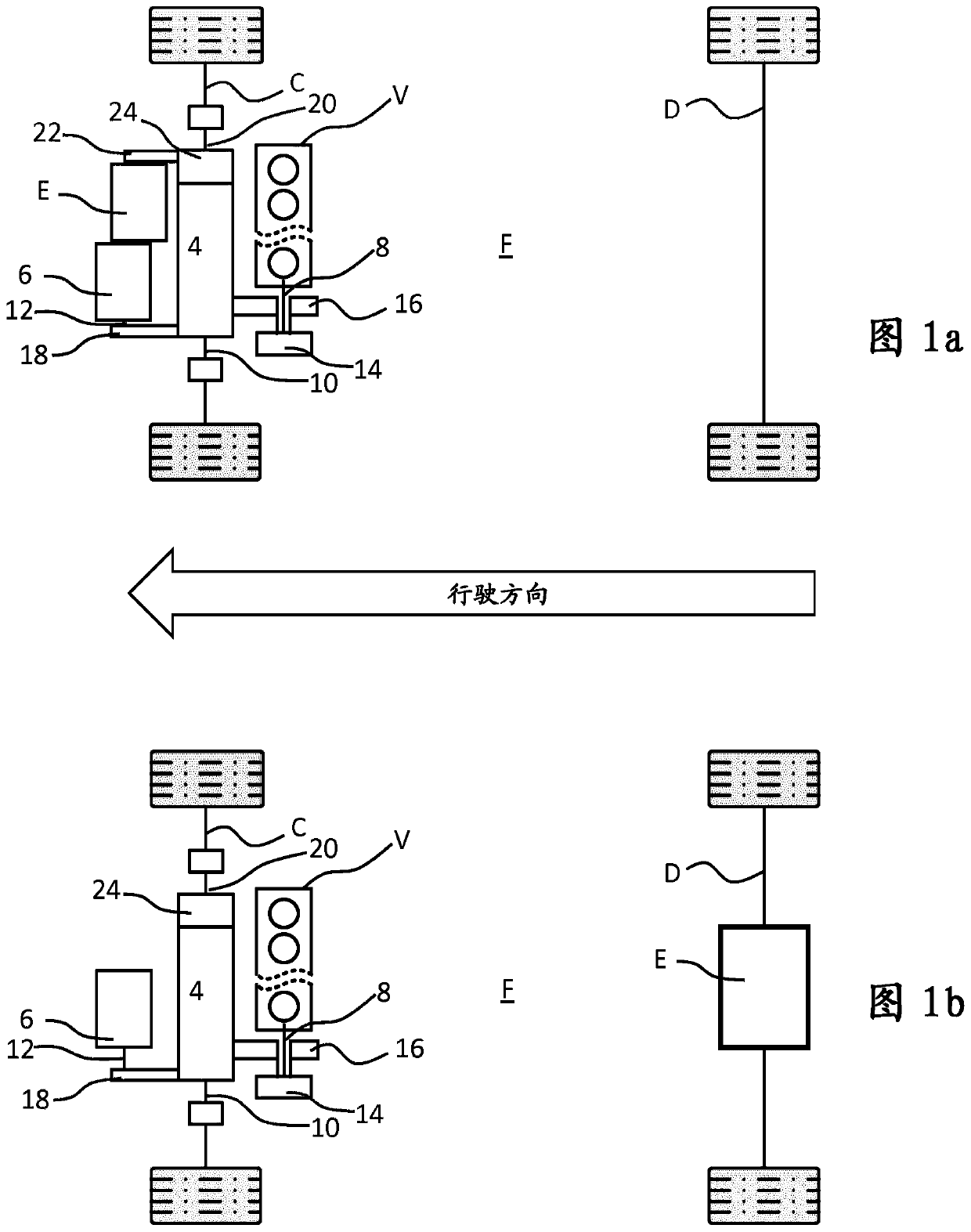
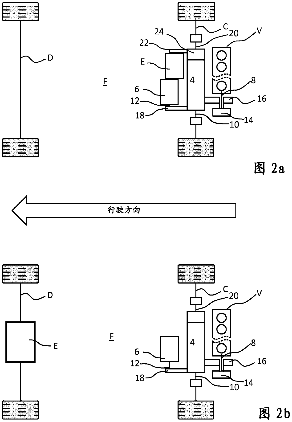
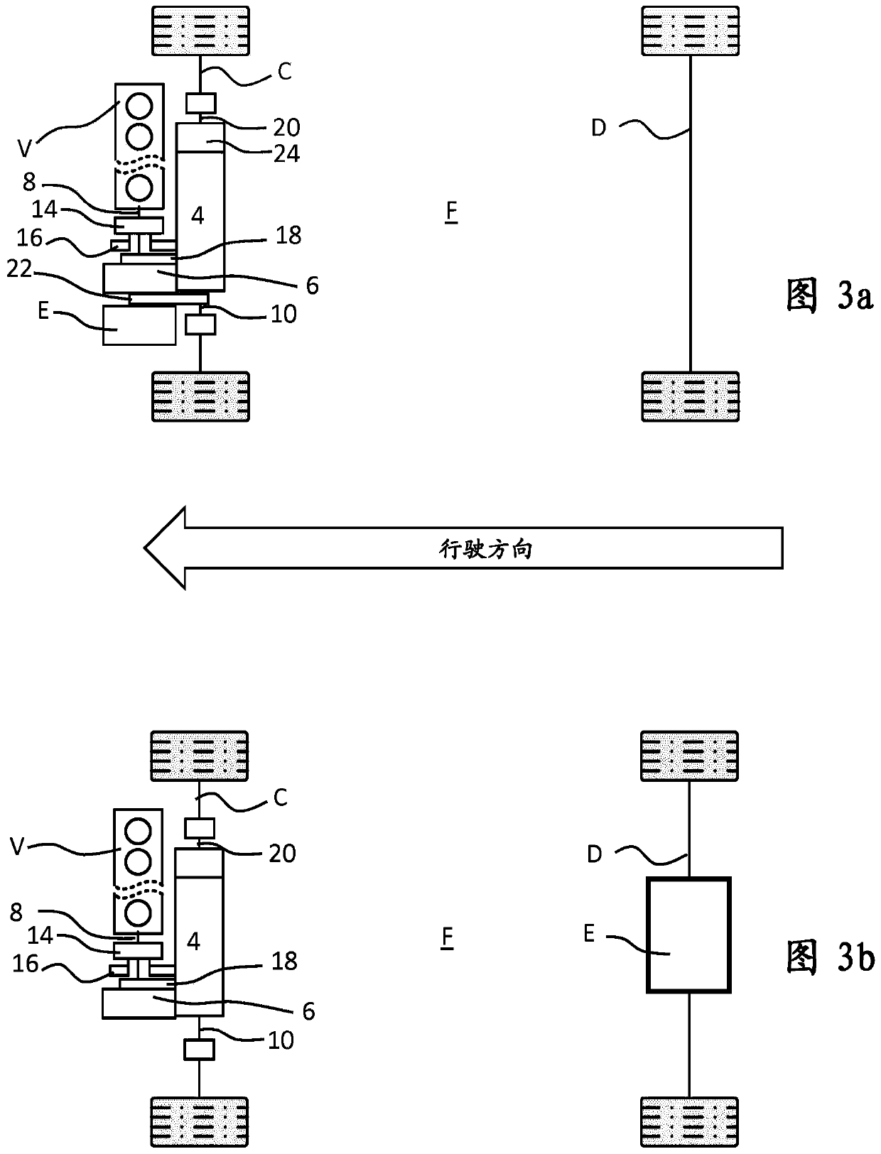
[0038] FIGS. 1 to 3 show, in sub-figures a and b, schematic representations of two variants of a vehicle 100 with a hybrid drive train 1 , wherein the hybrid drive train 1 has two drive units, namely an internal combustion engine V and a Motor E. The two drive units V and E provide torque with which drive shafts C and / or D and thus at least one wheel can be driven. Here, the variants of sub-figures a and b differ in that, in variant a, the internal combustion engine V and the electric motor E drive the same drive shaft C; in variant b, the internal combustion engine V and the electric motor E drive different shafts C and D. Furthermore, it can be seen from the figure that the hybrid drive train comprises a transmission 4 with a transmission input shaft 10 in order to transmit torque from the internal combustion engine V via its internal combustion engine drive shaft 8 on the transmission input side to the transmission input shaft 10 and in the transmission The output side is...


PUM


Abstract

The invention relates to a hybrid drive train (1) for a vehicle (100), comprising: at least one internal combustion engine (V) having an internal combustion engine drive shaft (8), in particular a crankshaft, and at least one first electrical machine (E) having a first electrical machine drive shaft (12), the internal combustion engine (V) and the first electrical machine (E) being designed to transfer a torque to at least one drive axle (C, D), and also comprising a transmission (4) having a transmission input shaft (10) and a transmission output shaft (20), which is operatively connected toa first drive axle (C) that can be driven by the internal combustion engine (V), the transmission input shaft (10) of the transmission (4) being connected at least to the internal combustion engine drive shaft (8) of the internal combustion engine (V) in order to transfer a torque from the internal combustion engine (V) to the transmission input shaft (10) and further to the first drive axle (C),the transmission input shaft (10) and the internal combustion engine drive shaft (8) of the internal combustion engine (V) being arranged parallel to each other.

Description

technical field [0001] The invention relates to a hybrid drive train for a vehicle comprising: at least one internal combustion engine, an electric machine and a transmission. Background technique [0002] In known hybrid powertrain transmissions, the drive shaft of the internal combustion engine, in particular the crankshaft, is usually connected directly or indirectly to the transmission input shaft via a clutch device, wherein the transmission and the internal combustion engine are connected along the axis with respect to the power flow from the internal combustion engine to the transmission. set next to each other. The at least one electric machine can also be arranged axially next to the internal combustion engine or the transmission, but it is also known to arrange the electric machine and its drive shaft with an axis parallel to the transmission or the internal combustion engine. Through such an axis-parallel arrangement, installation space can be saved in the longit...

Claims


Application Information

Patent Timeline
Patent Type & Authority Applications(China)
IPC IPC(8): B60K6/48B60K6/365B60K6/52B60K6/40B60K6/405B60K6/387B60K6/38B60K1/02
CPCB60K6/365B60K6/38B60K6/40B60K6/405B60K6/48B60K6/52B60W30/184B60W30/1846B60K2006/4825B60W2030/206Y02T10/62B60K1/02B60K6/24B60K6/26B60K6/30B60K6/543B60K17/22B60Y2200/92
Inventor U·奥内穆斯B·克卢格F·波比策
Owner BAYERISCHE MOTOREN WERKE AG
Why Eureka
Try Eureka