Hard coat film, optical layered body, and image display device

A technology of optical laminates and hard coatings, applied in coatings, optics, optical components, etc., can solve the problems of easy and obvious peeling between layers, and achieve the effects of excellent adhesion, improved visibility, and less coloring

Active Publication Date: 2020-05-19
NITTO DENKO CORP
View PDF15 Cites 1 Cited by
  • Summary
  • Abstract
  • Description
  • Claims
  • Application Information

AI Technical Summary

Problems solved by technology

Especially in an environment exposed to ultraviolet rays such as outdoors

Method used


Image

  • Hard coat film, optical layered body, and image display device
  • Hard coat film, optical layered body, and image display device
  • Hard coat film, optical layered body, and image display device

Examples


Example Embodiment

[0094] Example

[0095] Hereinafter, the present invention will be explained in more detail with examples, but the present invention is not limited by the following examples.

[0096] [Evaluation method]

[0097]

[0098] The arithmetic mean surface roughness Ra of the hard coat layer was measured under the following conditions using an atomic force microscope (AFM).

[0099] Device: Dimemsion3100 manufactured by Bruker, Controller: NanoscopeV

[0100] Measurement mode: tap mode

[0101] Cantilever: single crystal Si

[0102] Measurement field: 1μm×1μm

[0103]

[0104] A black acrylic sheet (manufactured by Mitsubishi Chemical Co., Ltd.) with a thickness of 2 mm was attached to the main surface of the hard coat film without a hard coat layer using a transparent acrylic adhesive to create a diffuse reflectance spectrum (SCE) spectrum. ) Sample for measurement. The self-hard coating is formed and the sample is irradiated with light from the D65 light source. The diffuse reflectance spectr...


PUM

PropertyMeasurementUnit
Particle sizeaaaaaaaaaa
Roughnessaaaaaaaaaa
Thicknessaaaaaaaaaa

Abstract

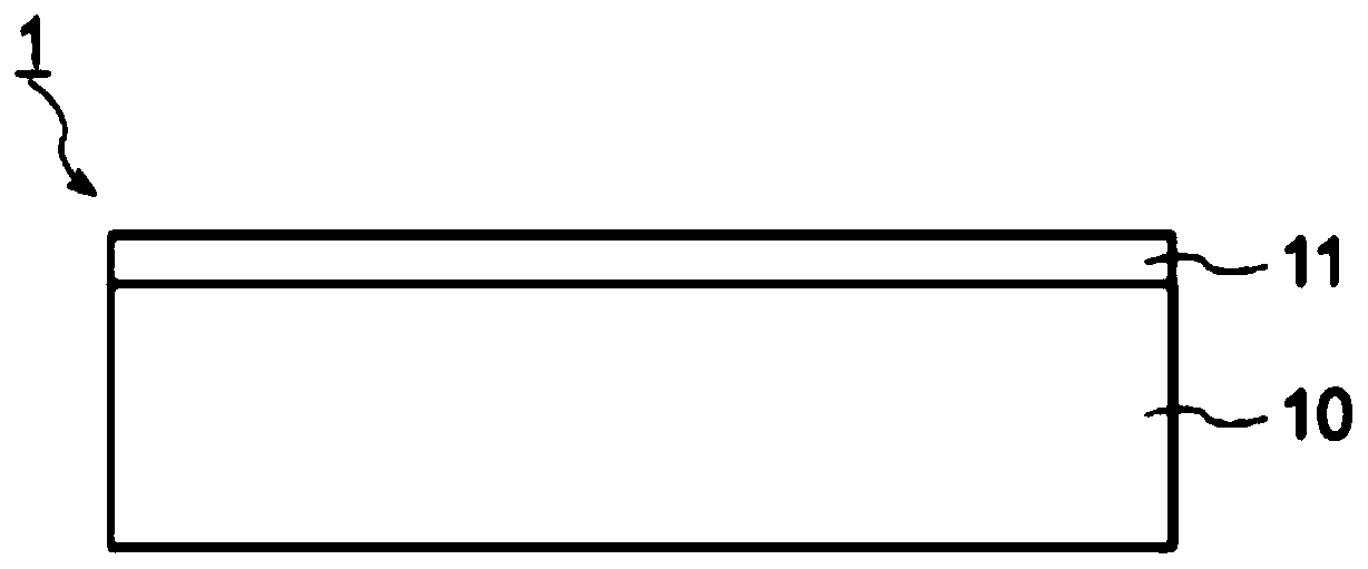
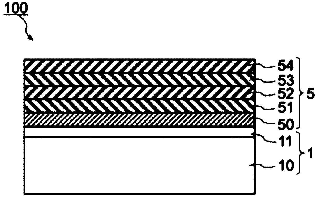
A hard coat film (1) is provided with a hard coat layer (11) on one principal surface of a film substrate (10). The hard coat layer includes a binder resin and an inorganic filler, the content of theinorganic filler with respect to 100 parts by weight of the binder resin 100 being 20-80 parts by weight. The average primary particle diameter of the filler is preferably 25-70 nm. The arithmetic mean roughness of the surface of the hard coat layer is preferably at least 2 nm. The b* of diffuse reflected light from the hard coat layer is preferably -0.2 or greater.

Description

technical field [0001] The present invention relates to a hard coat film and an optical laminate in which an inorganic thin film is provided on the hard coat film. Background technique [0002] In some cases, a hard coat layer is provided on a film arranged on the identification side surface of an image display device such as a liquid crystal display or an organic EL (Electroluminescence, electroluminescence) display, or a film used for bonding to a window glass to prevent the Damage caused by contact, etc. Various functions can be imparted by providing an inorganic thin film on the hard coat layer. For example, an antireflection film can be obtained by providing an antireflection layer comprising a multilayer film having a different refractive index on the hard coat layer of the hard coat film. [0003] In an optical laminate including an inorganic thin film layer on a hard coat layer, the interlayer adhesion force between the hard coat layer and the inorganic layer is sm...

Claims


Application Information

Patent Timeline
IPC IPC(8): G02B1/14G02B1/115G02B1/18B32B7/023B32B27/00B32B27/18
CPCB32B7/023B32B27/00B32B27/18G02B1/115G02B1/14G02B1/18C08J7/046C08J7/0423C08J5/18C09D7/61C09D1/00C09D5/004C09D5/16C08K2201/011
Inventor 高见佳史横井辽太郎梨木智刚
Owner NITTO DENKO CORP
Why Eureka
Try Eureka