Flue gas desulfurization device and flue gas desulfurization method

A desulfurization device and flue gas technology, which can be used in combination devices, separation methods, chemical instruments and methods, etc., can solve problems such as low removal efficiency, and achieve the effects of high removal efficiency, simple equipment and compact layout.

Pending Publication Date: 2020-05-22
BEIJING ZHTY TECH CO LTD
View PDF0 Cites 0 Cited by
  • Summary
  • Abstract
  • Description
  • Claims
  • Application Information

AI Technical Summary

Problems solved by technology

[0006] The object of the present invention is to provide a flue gas desulfurization device to solve the problem of low SO3 removal efficiency in existing flue gas desulfurization devices

Method used


Image

  • Flue gas desulfurization device and flue gas desulfurization method

Examples


Embodiment Construction

[0032] In order to make the objectives, technical solutions and advantages of the present invention clearer, the present invention will be described in detail below with reference to the accompanying drawings and specific embodiments.

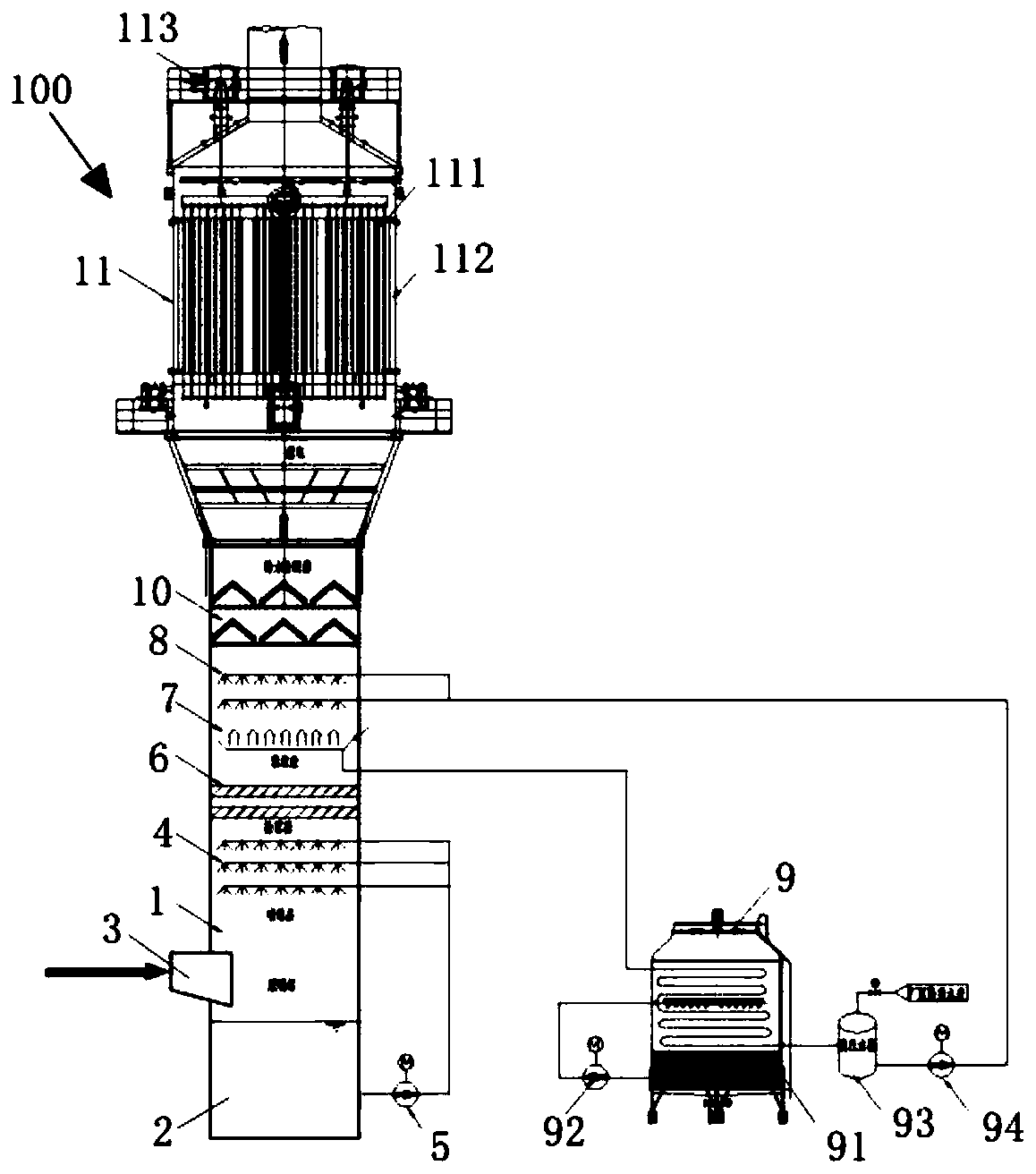
[0033] Such as figure 1 As shown, the flue gas desulfurization device 100 of the present invention includes: a desulfurization tower 1, a slurry tank 2, an air inlet 3, a spray layer 4, a slurry circulation pump 5, a mist eliminator 6, a liquid collecting pan 7, a water washing cooling layer 8, Condensation circulation system 9, dewatering and deacidification device 10, and wet electric precipitator 11.

[0034] The slurry tank 2 is arranged at the bottom of the desulfurization tower 1, the gas inlet 3 is connected with the desulfurization tower 1 and is located above the slurry tank 2, and the spray layer 4 is arranged above the gas inlet 3, For spraying the desulfurization slurry, the mist eliminator 6 is arranged above the spray layer 4 to inter...


PUM

PropertyMeasurementUnit
Cut circle diameteraaaaaaaaaa

Abstract

The invention provides a flue gas desulfurization device. The flue gas desulfurization device comprises a desulfurization tower; a slurry tank arranged at the bottom of the desulfurization tower; a gas inlet communicated with the desulfurization tower and positioned above the slurry pool; a spraying layer arranged above the gas inlet and used for spraying desulfurization slurry; a demister arranged above the spraying layer and used for intercepting the droplet-shaped desulfurization slurry; a liquid collecting tray arranged above the demister; a washing cooling layer arranged above the liquidcollecting tray and used for spraying low-temperature condensate water; a water and acid removal device arranged above the washing cooling layer and used for removing large-particle-size sulfur trioxide liquid drops and dust after coagulation; and a wet electric dust remover arranged above the water and acid removal device and used for removing small-particle-size sulfur trioxide liquid drops anddust escaping from the water and acid removal device. The flue gas desulfurization device disclosed by the invention is compact in layout, small in occupied area and suitable for various transformation projects with limited places.

Description

Technical field [0001] The invention relates to a flue gas desulfurization device and a flue gas desulfurization method. Background technique [0002] SO 3 The generation of sulphur is very complicated, mainly depends on the boiler's combustion, fuel composition, operating parameters, desulfurization, denitrification facility operating conditions, etc. During the combustion process of fossil fuels in coal-fired boilers, almost all combustible sulfur will be oxidized into gaseous SO 2 And SO 3 , Most of which are SO 2 , SO 3 About SO 2 About 1 to 5%. For most of the coal-fired boiler flue gas, SCR denitration + wet desulfurization, SO 2 Will be converted into SO under the action of denitration catalyst 3 ; The calcination of petroleum coke in the carbon industry produces extremely high sulfur oxides (SOx), of which SO 3 The proportion is relatively high. [0003] When containing gaseous SO 3 Or when the flue gas of H2SO3 passes through the wet flue gas desulfurization system, the f...

Claims


Application Information

Patent Timeline
IPC IPC(8): B01D53/14B01D50/00
CPCB01D53/1481B01D50/00
Inventor 陈晶邓云波张杰
Owner BEIJING ZHTY TECH CO LTD
Why Eureka
Try Eureka