
Micro and fine high-frequency grouped pulse power supply

A kind of pulse power supply and micro-technology, which is applied in the direction of electric pulse generator circuit, energy storage components to generate pulses, electrical components, etc., can solve the problems of reduced surface roughness in processing efficiency, large discharge pulse interval coefficient, and low processing efficiency. Solve the effect of processing efficiency and surface roughness, increase discharge frequency, and reduce development cost

Active Publication Date: 2020-05-22
NANJING UNIV OF SCI & TECH
View PDF13 Cites 3 Cited by
  • Summary
  • Abstract
  • Description
  • Claims
  • Application Information

AI Technical Summary

Problems solved by technology

[0004] The existing micro spark pulse power supply is mostly RC type pulse power supply. The basic idea is that the DC source charges the capacitor through the resistance, and then uses the capacitor to discharge the gap. Due to the discharge time, the discharge pulse interval coefficient is too large, and the processing efficiency is very low; the DC source is isolated from the discharge gap without switching elements, which affects the discharge stability; at the same time, because the resistance in the circuit consumes most of the energy, the power utilization rate is very low, often not more than 36%
In order to overcome the shortcomings of the existing micro electric spark pulse power supply and solve the contradiction between processing efficiency and surface roughness reduction, it is of great scientific significance and practical value to carry out research on new micro electric spark pulse power supply

Method used


Image

  • Micro and fine high-frequency grouped pulse power supply
  • Micro and fine high-frequency grouped pulse power supply
  • Micro and fine high-frequency grouped pulse power supply

Examples


Embodiment Construction

[0026] The solution of the present invention will be further described in detail below in conjunction with the accompanying drawings.

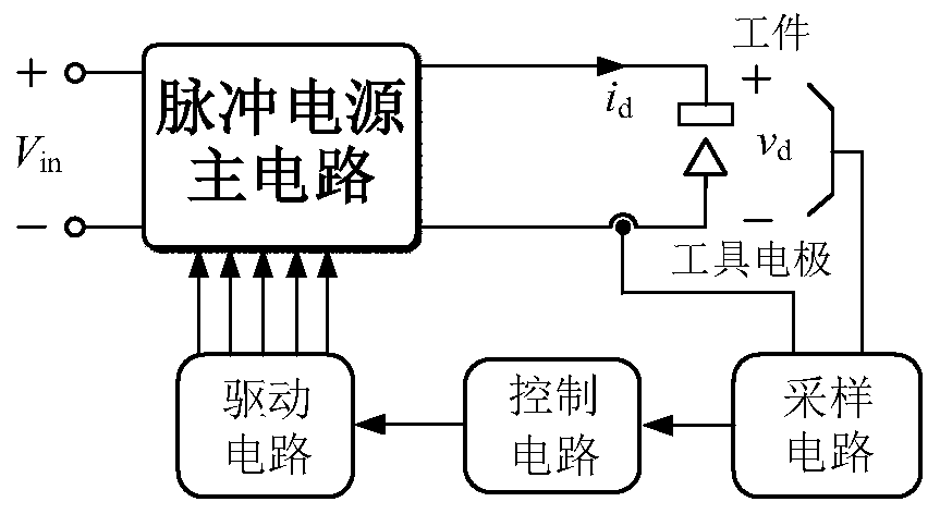
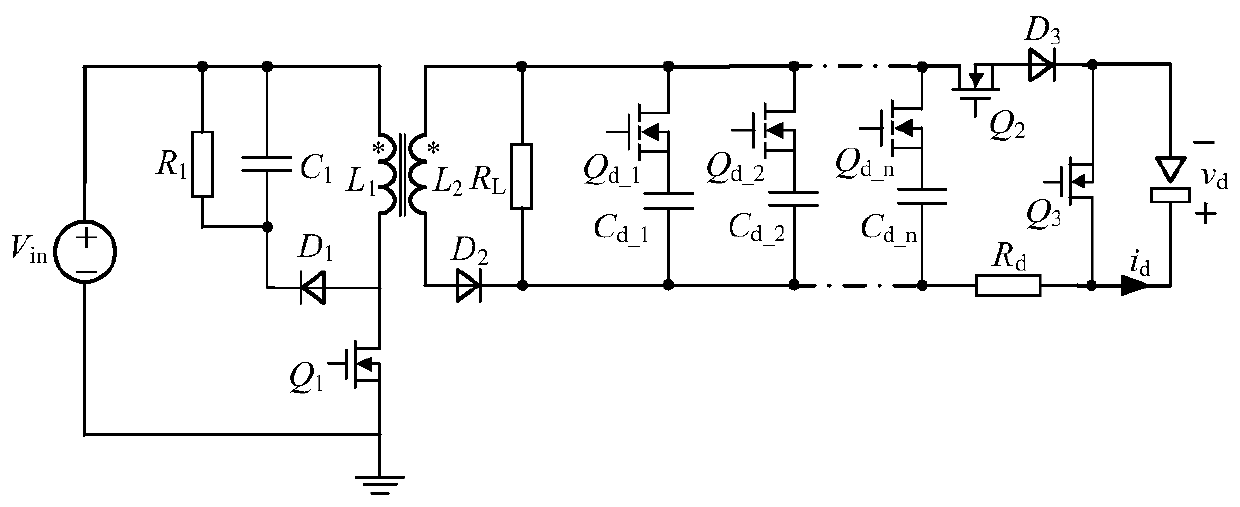
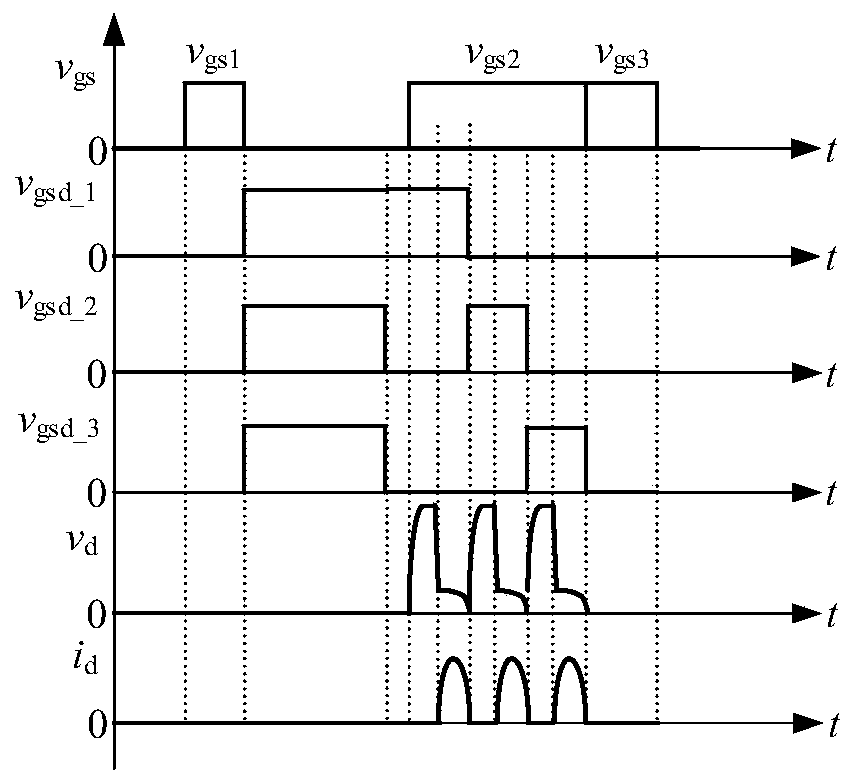
[0027] Such as figure 1 As shown, the micro-high-frequency group pulse power supply of the present invention includes a DC power supply, a pulse power supply main circuit, a gap voltage and current sampling circuit, an FPGA control circuit, and a drive circuit; The voltage and gap current are sampled, and the sampling signal is input to the FPGA control module, and the calculation is performed according to the processing requirements to generate a PWM signal, which is filtered and amplified by the drive circuit and then respectively driven to drive the primary switch tube Q in each circuit of the pulse power supply 1 , micro-discharge switch tube Q 2 , Disconnect switch tube Q 3 , the switching tube Q connected in series with the discharge capacitor d_1 to Q d_n , so as to realize high-frequency and adjustable pulse width EDM pulse wavefor...


PUM


Abstract

The invention discloses a micro and fine high-frequency grouped pulse power supply. The micro and fine high-frequency grouped pulse power supply comprises a direct-current power supply, a pulse powersupply main circuit, a gap voltage and current sampling circuit, an FPGA control circuit and a driving circuit, and the circuit pulse power supply main circuit comprises a flyback transformer, a primary side switch tube, a micro and fine discharge switch tube, an electricity elimination off-switch tube, first to nth switch tubes, a first resistor, a clamping capacitor, a first diode, a second resistor, a third resistor, a second diode, a third diode, and first to nth capacitors. The pulse power supply main circuit provides energy for the gap load, the gap voltage and current sampling circuit samples voltage and gap current at two ends of a gap, the FPGA control module generates PWM signals according to the sampled voltage and current, and the PWM signals are filtered and amplified by the driving circuit to drive the pulse power supply main circuit to be switched on and off. The flyback circuit is adopted to charge the discharge capacitor, input and output are isolated, discharge is notaffected by input voltage, and multi-level energy processing is achieved within a certain range.

Description

technical field [0001] The invention relates to a fine high-frequency pulse power supply, in particular to a fine high-frequency group pulse power supply. Background technique [0002] In recent years, my country's EDM technology has developed rapidly. It is currently the country with the largest output and ownership of EDM machines in the world, but it is also the largest importer of EDM machines, and has a deficit in the international trade of EDM machines. This is mainly because there is still a certain gap between my country and the international advanced level in the development and production of high-end precision electric machining machine tools. Therefore, the research on related technologies of high-end precision electric machining machine tools, especially the pulse power supply technology for micro-EDM is imminent. [0003] For micro EDM, the use of small and controllable single pulse discharge energy can better improve the machining accuracy and surface quality....

Claims


Application Information

Patent Timeline
IPC IPC(8): H02M9/04H02M3/335H03K3/57
CPCH02M11/00H02M3/33523H03K3/57
Inventor 杨飞覃徳凡汪志鹏史顺飞吴鹏程邵佳钰李宏良李磊
Owner NANJING UNIV OF SCI & TECH
Learn More