
Method for testing the high-resolution three-dimensional refractive index of microstructure optical fiber

A micro-structured optical fiber and high-resolution technology, which is applied in the measurement of phase influence characteristics, etc., and can solve problems such as complex and complicated devices

Inactive Publication Date: 2020-05-26
GUILIN UNIV OF ELECTRONIC TECH
View PDF17 Cites 0 Cited by
  • Summary
  • Abstract
  • Description
  • Claims
  • Application Information

AI Technical Summary

Problems solved by technology

[0011] Patent CN201710518263.5 discloses a three-refractive index tomographic microscopic imaging system and its method. Although it can restore the three-dimensional refractive index information of the sample, it is essentially different from the present invention in the imaging optical path, and the required devices more complicated
[0012] Patent CN201710904860.1 discloses an optical coherence tomography imaging system, which uses Mach-Zehnder interference optical path, which is characterized by the use of optical fibers to simplify the system and reduce costs, but compared with the optical path structure of the F-P cavity, it is still relatively complex

Method used


Image

  • Method for testing the high-resolution three-dimensional refractive index of microstructure optical fiber
  • Method for testing the high-resolution three-dimensional refractive index of microstructure optical fiber
  • Method for testing the high-resolution three-dimensional refractive index of microstructure optical fiber

Examples


Embodiment 1

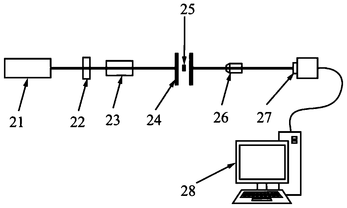
[0064] Figure 2b An embodiment of digital holographic recording optical path based on F-P cavity is given. The optical path includes a light source 21 , an attenuator 22 , a beam expander 23 , an F-P etalon 24 , a microstructured optical fiber 25 , a microscope objective lens 26 , a CCD 27 and a computer 28 . The light beam starts from the light source 21, passes through the attenuator 22, and the energy of the light beam weakens, the light beam passes through the beam expander 23, and the diameter of the light beam expands, and when the light beam passes through the F-P etalon 24 with the microstructured optical fiber 25, it is repeatedly reflected at the F-P etalon 24, After passing through the microstructured optical fiber 25 multiple times, each beam of transmitted light passing through the F-P etalon 24 passes through the microscope objective lens 26, and then interferes and superimposes on the CCD 27. The digital hologram of the interference is recorded by the CCD 27 an...


PUM


Abstract

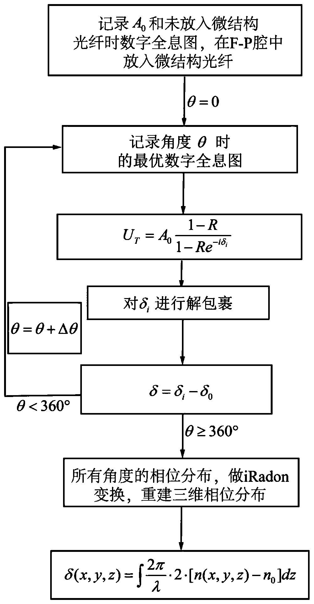
The invention provides a method for testing the high-resolution three-dimensional refractive index of a microstructure optical fiber. The method is characterized by comprising digital hologram recording based on an F-P cavity, numerical reconstruction, unwrapping, error processing, three-dimensional phase distribution reconstruction and three-dimensional refractive index conversion. Compared witha traditional microscopic imaging method, the invention has the advantages of being simple in structure, high in sensitivity and accurate in measurement. The method can be used for high-resolution three-dimensional microscopic imaging of the microstructure optical fiber, and can be widely applied to nondestructive, unmarked and non-contact three-dimensional tomography and the like of optical transparent objects.

Description

[0001] (1) Technical field [0002] The invention relates to a high-resolution three-dimensional refractive index testing method of microstructured optical fibers, which can be used for high-resolution three-dimensional microscopic imaging of microstructured optical fibers, and can be widely used in non-destructive, non-marking and non-contact optical transparent objects. Three-dimensional tomography and the like belong to the technical field of microscopic imaging. [0003] (2) Background technology [0004] The three-dimensional refractive index distribution of microstructured optical fiber is an important inherent attribute. For optically transparent microstructured optical fiber, the three-dimensional refractive index distribution can reflect the microstructure, density and other information of the sample. Labeled, non-contact 3D tomography. [0005] In contemporary life science research, fluorescence imaging is usually used to label the samples to be tested. However, in ...

Claims


Application Information

Patent Timeline
Patent Type & Authority Applications(China)
IPC IPC(8): G01N21/41
CPCG01N21/41
Inventor 苑立波孟令知李晟
Owner GUILIN UNIV OF ELECTRONIC TECH
Learn More