A design method for pile-sheet wall structure of friction-stressed embankment

A design method and pile-slab structure technology, applied to underwater structures, foundation structure engineering, roads, etc., can solve the problems of high project investment, limited seismic performance, and difficult deformation of soil foundation reinforcement piles, etc., to achieve good safety, Improve the effect of force mode, good resistance to deformation and shock resistance

Active Publication Date: 2021-05-11
CHINA RAILWAY ERYUAN ENG GRP CO LTD
View PDF7 Cites 0 Cited by
  • Summary
  • Abstract
  • Description
  • Claims
  • Application Information

AI Technical Summary

Problems solved by technology

[0005] The purpose of the present invention is to provide a solution to solve the problems of hard-to-control deformation of soil foundation reinforcement piles in the existing pile-slab wall structure, limited seismic performance, large construction safety risks and high engineering investment of deep and long-section reinforcement piles. A design method for a pile-sheet wall structure of a friction-loaded embankment, which makes the pile-sheet-wall structure of a friction-loaded embankment have better anti-deformation and earthquake resistance when the reinforcement piles have the same specification and the same arrangement, and are safer and more reliable

Method used


Image

  • A design method for pile-sheet wall structure of friction-stressed embankment
  • A design method for pile-sheet wall structure of friction-stressed embankment
  • A design method for pile-sheet wall structure of friction-stressed embankment

Examples


Embodiment 1

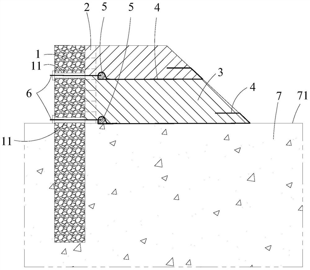
[0054] Such as Figure 2-3 As shown, a calculation method for the pile-slab wall structure of a frictional force type embankment is based on the pile-slab wall structure, which is specifically: a plurality of reinforcement components are set in the embankment filling body 3, and the multiple reinforcement components combine the described The embankment filling body 3 is divided into several layers from top to bottom, and the reinforcement pile 1 is provided with several connection parts 11 corresponding to the reinforcement parts from top to bottom, and the reinforcement parts and the corresponding connection parts 11 pass through Tension anchor cable 6 is connected;

[0055] Include the following steps,

[0056] ① Determine the surface friction coefficient f between the bidirectional geogrid 4 of the i-th layer and the embankment filling body 3 ci ;

[0057] ②Calculate the load W of the embankment filling body 3 overlying the bidirectional geogrid 4 of each layer from top ...

Embodiment 2

[0072] Such as Figure 2-3 As shown, this embodiment is described with an actual engineering example:

[0073] A pile-slab wall construction site of an embankment, the embankment filling height is 6m, the same kind of filler is used, and the bulk density of the filler is 20kN / m 3 , internal friction angle Take 25°, cohesion c take 20kPa, foundation soil filler bulk density 19kN / m 3 , internal friction angle Take 35°, cohesion c take 10kPa, two-way geogrid 4 is set in 2 layers (ground layer width 23m, tensile strength 160kN / m, 3m layer in the middle of embankment, width 18m, tensile strength 120kN / m), force transmission The shear strength of the bar is 800kN at the ground and 400kN at the middle of the embankment, and the vertical spacing of reinforcement piles 1 is 6m.

[0074] A calculation method for an embankment pile-slab wall structure described in the present embodiment comprises the following steps,

[0075] ①Determine the surface friction coefficient f between t...


PUM


Abstract

The present invention relates to the field of embankment engineering, in particular to a design method for a friction-stressed embankment pile-sheet wall structure, comprising the following steps: converting the surface friction force between each of the reinforcement components and the embankment filling body into Concentrate the effective tension; determine the design parameters of the reinforced pile. The design method of the pile-sheet wall structure of a friction-stressed embankment of the present invention enables the reinforced piles to bear relatively large concentrated effective tension in layers in their length direction, and compared with the prior art reinforced piles, it greatly improves the strength of the reinforced piles. Moreover, the reinforcement piles are connected with the reinforcement components in layers and at multiple points, so that the reinforcement piles have better anti-deformation and anti-seismic capabilities when resisting the earth pressure generated by the embankment filling body, that is, at the same Under the requirement of deformation and anti-seismic capability, the size of the required reinforcement pile is smaller than that of the prior art reinforcement pile, and since the main stress point of the reinforcement pile is determined, the safety of the reinforcement pile is better controlled.

Description

technical field [0001] The invention relates to the field of embankment engineering, in particular to a design method for a pile-sheet wall structure of a friction-bearing embankment. Background technique [0002] At present, in the field of subgrade engineering, the pile-slab wall structure is widely used in subgrade engineering because of its good embankment slope closing effect and good seismic performance. [0003] Such as figure 1 As shown, the currently commonly used pile-slab wall structure includes an embankment filling body 3 arranged on the foundation 7, and one side of the embankment filling body 3 is provided with a soil retaining board 2, and the outer side of the soil retaining board 2 extends along it. Several reinforcement piles are arranged at intervals in the direction, and the lower part of the reinforcement piles is buried in the foundation 7 . [0004] In the soil foundation, due to the large horizontal deformation of the reinforcement piles in the exi...

Claims


Application Information

Patent Timeline
Patent Type & Authority Patents(China)
IPC IPC(8): E01C3/04E02D29/02
CPCE01C3/04E02D29/02
Inventor 姚裕春袁碧玉封志军陈伟志张耀
Owner CHINA RAILWAY ERYUAN ENG GRP CO LTD
Why Eureka
Try Eureka