Armor type steel plate concrete shear wall and construction scheme thereof

A steel plate concrete and reinforced concrete technology, applied to walls, building components, buildings, etc., can solve the problems of reducing the long-term performance and durability of structures, insufficient strength, and increasing the stability of columns, so as to improve long-term performance and durability, reduce Welding residual stress and the effect of maintaining continuous energy dissipation capacity

Inactive Publication Date: 2018-06-15
王斐
View PDF9 Cites 0 Cited by
  • Summary
  • Abstract
  • Description
  • Claims
  • Application Information

AI Technical Summary

Problems solved by technology

This means that during the process of large wind load or earthquake, there is noise, which affects the living comfort of the building
The traditional steel plate shear wall mainly relies on the tension field formed after buckling to resist the horizontal force, and the tension field anchored on the frame will generate additional bending distance to the side column and side beam, which increases the stability burden of the column
At the same time, the thin steel plate shear wall buckles under a small shear force, and the hysteresis loop has a significant pinch, which reduces the energy dissipation capacity of the steel plate shear wall
[0004] Through the research on the composite steel plate shear wall, it is found that there are the following problems: ①The reinforced concrete cover plate of the traditional composite steel plate shear wall is completely bonded to the embedded wall panel, and participates in resisting part of the horizontal force when the wall panel is restrained, but Due to the uncoordinated deformation of the inner filling steel plate and the concrete slab under large deformation, it is easy for the reinforced concrete cover slab to bear a large tensile stress. In addition, the out-of-plane extrusion of the steel plate leads to the continuous separation of the concrete and the steel plate, and the loss of the protection of the concrete slab The role of the inner filling steel plate, the later performance is still degraded to thin steel plate wall
③ Destruction of concrete reduces the long-term performance and durability of the structure
But there are the following disadvantages: ①The concrete slab is fixed by the friction generated by nuts or elastic materials and the inner surface of the installation hole of the concrete slab
This connection method is not strong enough, the binding force on the middle steel plate is not enough, and the buckling deformation of the steel plate cannot be effectively restrained
②Due to the existence of errors in reinforced concrete processing and steel plate processing, the possibility of inserting a large number of pull bolts into the concrete slab at one time at one time is a small probability event. It is necessary to debug and adjust the installation holes on the concrete slab on site, which is time-consuming and labor-intensive.
③The reinforced concrete cover slab is bulky and difficult to transport and install, which seriously restricts the application range of this kind of shear wall
④The reinforced concrete cover plate is bulky and has many installation holes. The position between the reinforced concrete cover plate and the steel plate is over-positioned. force broken off

Method used


Image

  • Armor type steel plate concrete shear wall and construction scheme thereof
  • Armor type steel plate concrete shear wall and construction scheme thereof
  • Armor type steel plate concrete shear wall and construction scheme thereof

Examples


Embodiment Construction

[0059] The present invention will be described below through specific examples, but the present invention is not limited thereto.

[0060] Below in conjunction with accompanying drawing, the present invention is described in further detail:

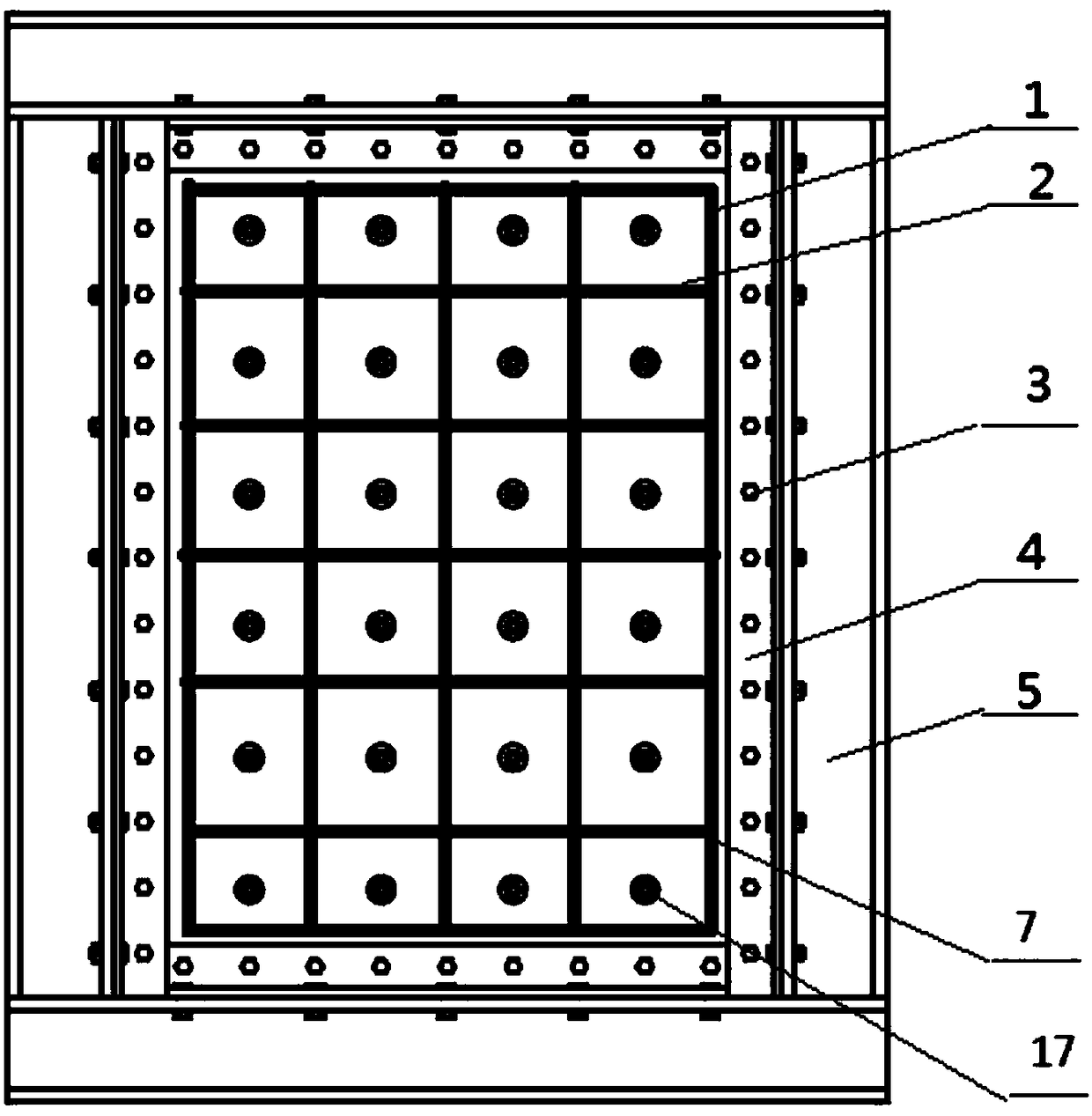
[0061] The combined steel plate shear wall structure of the present invention includes: edge components, angle steel, elastic rubber rings, concrete steel plate components and screw components. The specific construction plan is carried out in the following steps:

[0062] (1) The construction of the framework. The two ends of the first vertical edge member are respectively connected with the left end of the first horizontal edge member and the left end of the second horizontal edge member, wherein the left end of the first horizontal edge member and the left end of the second horizontal edge member are connected with the first vertical edge member The two ends of the second vertical edge member are respectively connected with the right ...


PUM


Abstract

The invention discloses an armor type steel plate concrete shear wall. The armor type steel plate concrete shear wall comprises five parts of an edge component, angle iron, an elastic rubber ring, a reinforced concrete steel plate and a screw assembly. The steel plate concrete shear wall can reduce external deformation of the steel plate face in the middle; the elastic rubber ring allows a concrete cover plate and the steel plate to generate relative movement, accordingly the tensile stress of the concrete cover plate is reduced, and the cover plate is prevented from being broken and falling off untimely; and the reinforced concrete cover plate is formed through assembly of divisional blocks, and thus transporting and mounting are convenient. The invention further provides a construction scheme of the armor type steel plate concrete shear wall and comprises the following steps that a frame is built up; the steel plate in the middle is mounted; the concrete cover plate is prefabricated;the concrete cover plate is mounted; glass glue is glued; and finally the armor type steel plate concrete shear wall is obtained. The armor type steel plate concrete shear wall solves the problem ofbreakage and falling-off of the concrete cover plate, the reinforced concrete cover plate is formed through assembly of the divisional blocks, transporting and mounting are convenient, and the application prospect is wide.

Description

technical field [0001] The invention relates to the field of building structures, in particular to an armored steel plate concrete shear wall. Background technique [0002] The steel plate shear wall structure is a new type of lateral force-resisting system, which is evolved and developed on the basis of thin-web beam theory research, with the steel plate embedded in the frame as the basic structural unit. The steel plate shear wall has the following good superior properties: ① Large initial lateral stiffness, stable hysteretic performance, strong energy dissipation capacity, high ductility, and good resistance to deformation under cyclic loads. ②By improving its stiffness and ductility, it can achieve the matching with the material, ductility and stiffness of the outer frame, so as to achieve the purpose of double fortification. ③The setting of embedded steel plates in the steel plate wall can alleviate the ductility requirements of the frame beam-column joint area, reduce...

Claims


Application Information

Patent Timeline
Patent Type & Authority Applications(China)
IPC IPC(8): E04B2/56
CPCE04B2/56
Inventor 王斐李瑞锋李翰林李典王国庆李明
Owner 王斐
Why Eureka
Try Eureka