Visual physical experimental system and method for rock hydraulic fracturing plane problem

A technology of hydraulic fracturing and plane problem, applied in the field of physical simulation experiment system, can solve problems such as difficult to reflect the change of crack width, difficult to monitor the mechanical response of the rock, and in-situ stress difference, etc., to achieve the effect of improving the loading speed and accuracy

Active Publication Date: 2020-06-02
SHANDONG UNIV
View PDF7 Cites 27 Cited by
  • Summary
  • Abstract
  • Description
  • Claims
  • Application Information

AI Technical Summary

Problems solved by technology

It is generally believed that during the simultaneous propagation of multiple fractures, the mutual interference between adjacent fractures causes some fractures to lose their propagation stability.
[0005] 2. Except for some special cases, the actual shape of hydraulic fractures on site cannot be directly observed
However, the above method can only obtain the geometric shape of hydraulic fractures in the final static state, and there is great uncertainty in inferring the propagation process and mechanism based on the final fracture shape.
In particular, the stress shadow effect affects the closure of fractures, resulting in dynamic changes in fracture width, and it is difficult for the damaged specimen after fracturing to reflect the change in fracture width
[0008] 5. The current indoor hydraulic fracturing experiments mainly study the expansion and evolution of single fractures and the law of the influence of factors such as ground stress difference, confining pressure, and fracturing fluid viscosity. There are almost no simultaneous expansion and evolution of too many fractures. Experimental study of the interaction process
[0009] 6. The hydraulic fracturing experiment based on the original rock is difficult to monitor the mechanical response of the rock during the fracturing process, which limits the analysis and research on the fracture propagation mechanism

Method used


Image

  • Visual physical experimental system and method for rock hydraulic fracturing plane problem
  • Visual physical experimental system and method for rock hydraulic fracturing plane problem
  • Visual physical experimental system and method for rock hydraulic fracturing plane problem

Examples


Embodiment Construction

[0051] It should be pointed out that the following detailed description is exemplary and intended to provide further explanation to the present application. Unless defined otherwise, all technical and scientific terms used herein have the same meaning as commonly understood by one of ordinary skill in the art to which this application belongs.

[0052] It should be noted that the terminology used here is only for describing specific implementations, and is not intended to limit the exemplary implementations according to the present application. As used herein, unless the invention clearly states otherwise, the singular is intended to include the plural, and it should also be understood that when the terms "comprise" and / or "comprise" are used in this specification, they mean Indicate the presence of features, steps, operations, means, components and / or combinations thereof;

[0053] As introduced in the background technology, there are still the following problems in the appl...


PUM


Abstract

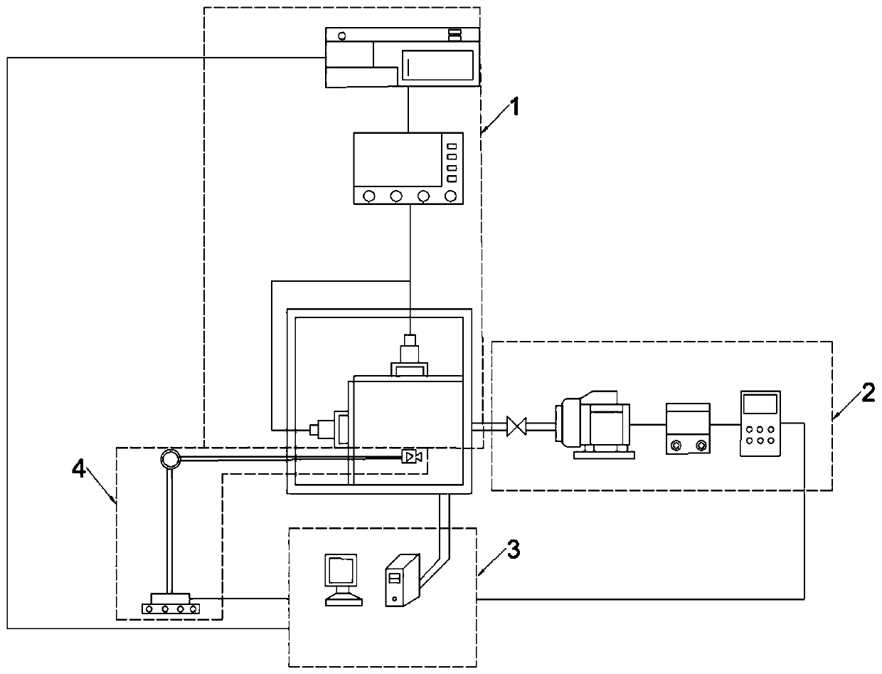
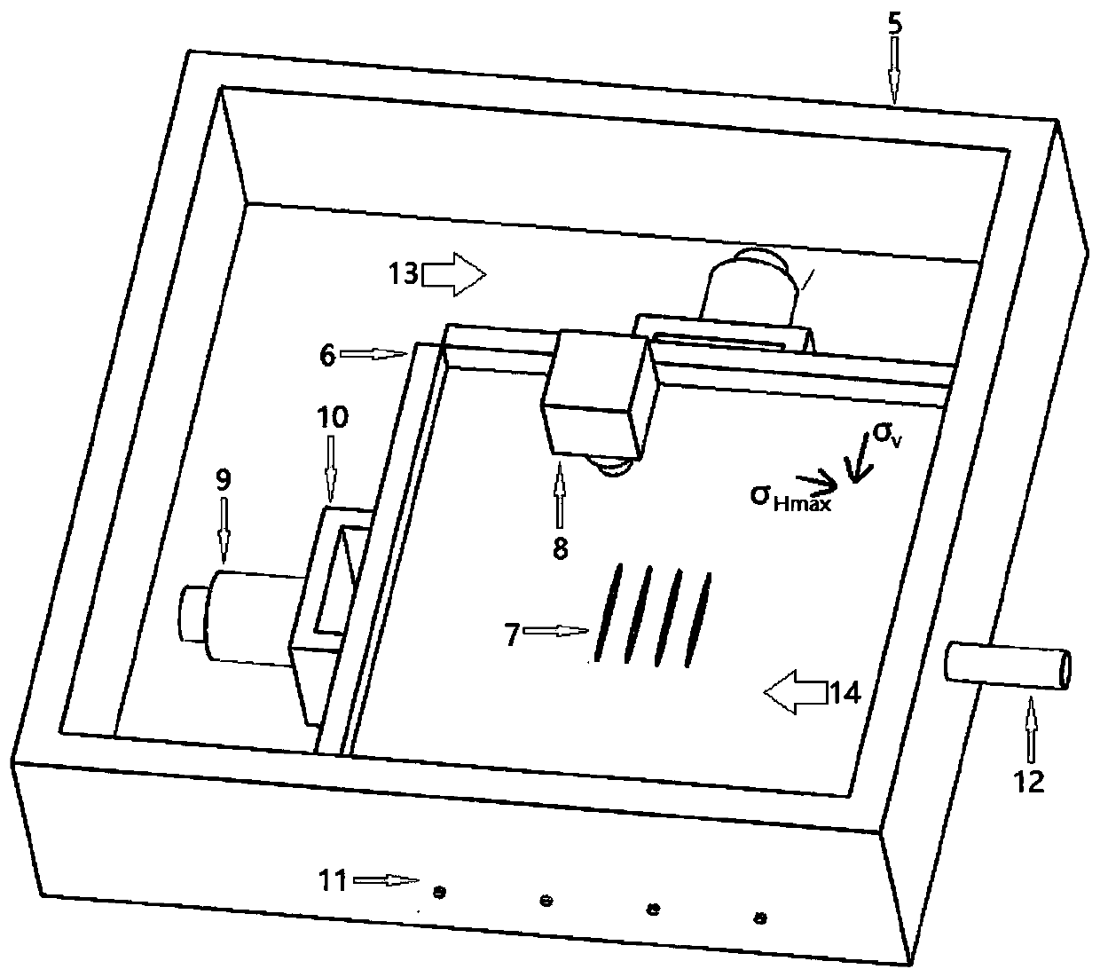
The invention discloses a visual physical experimental system and a visual physical experimental method for a rock hydraulic fracturing plane problem. The visual physical experimental system comprisesa crustal stress loading and control system, a hydraulic servo pump pressure system, a crack surface observation system, and an internal deformation and stress monitoring system, wherein the crustalstress loading and control system is used for applying confining pressure to s sample to simulate reservoir crustal stress; the hydraulic servo pumping system is used for pumping fracturing fluid intothe sample; the crack surface observation system is used for monitoring and recording a crack dynamic evolution process in the fracturing process and analyzing and processing the crack evolution process; and the internal deformation and stress monitoring system is used for monitoring an induced stress evolution rule and sample deformation characteristics in the sample in the hydraulic fracture propagation process. The visual physical experimental system and the visual physical experimental method can solve the problems existing in the rock hydraulic fracturing physical experiment, and play anirreplaceable important role in discovering a new multi-cluster fracturing phenomenon and revealing the inter-fracture rock mechanical response and competition mechanism.

Description

technical field [0001] The invention relates to a visual physical simulation experiment system and an experiment method for the simultaneous expansion plane problem of multi-cracks in rock hydraulic fracturing. Background technique [0002] Horizontal well staged multi-cluster simultaneous fracturing technology has become a key technology for the development of enhanced geothermal systems and low-permeability oil and gas stimulation. By performing multi-cluster perforation in the same fracturing section, multiple fractures are opened at one time, thereby increasing the volume of reservoir stimulation and reducing fracturing time and construction costs. The design purpose of multi-cluster fracturing is to simultaneously form a series of dense hydraulic fracture networks extending along the direction of the maximum principal stress to increase fluid exchange efficiency. Therefore, the geometry of hydraulic fracture propagation is the key to evaluating the effect of reservoir ...

Claims


Application Information

Patent Timeline
Patent Type & Authority Applications(China)
IPC IPC(8): G09B23/40
CPCG09B23/40Y02E10/10
Inventor 段抗王路超张强勇李雪剑周新宇
Owner SHANDONG UNIV
Why Eureka
Try Eureka