Concave-convex surrounding internal cooling type turbine generator end ventilation cooling system with multiple shields

A turbo-generator, ventilation and cooling technology, applied in the direction of magnetic circuit static parts, magnetic circuit shape/style/structure, etc., can solve the problems of lowering temperature and unreasonable ventilation design, saving materials and enhancing long-term safety and stability The ability to run, the effect of enhanced cooling

Active Publication Date: 2020-06-02
HARBIN UNIV OF SCI & TECH
View PDF7 Cites 0 Cited by
  • Summary
  • Abstract
  • Description
  • Claims
  • Application Information

AI Technical Summary

Problems solved by technology

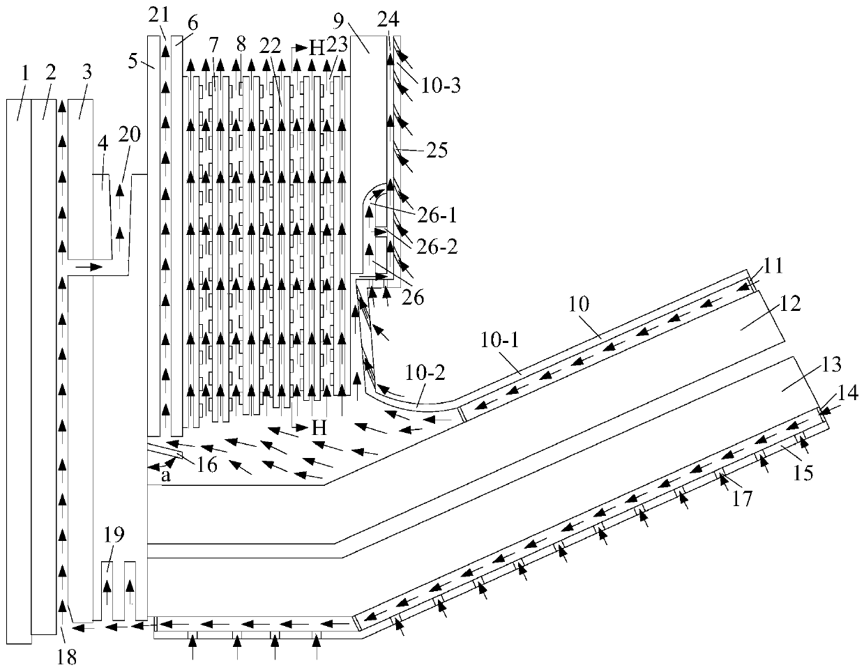
[0004] The purpose of the present invention is to provide a multi-shielded concave-convex surround internal cooling type turbogenerator end ventilation cooling system to solve the problems caused by the unreasonable ventilation design of the end area of ​​the large-capacity turbogenerator. The problem of loss and overheating of shielding, pressure ring, shielding pressure plate and iron core at the end of the stator effectively reduces the loss of various components in the end area of ​​the turbogenerator and improves the utilization rate of cooling gas in the end area , significantly reduces the temperature of the components at the end, and enhances the safe and reliable operation of large-capacity turbogenerators

Method used


Image

  • Concave-convex surrounding internal cooling type turbine generator end ventilation cooling system with multiple shields
  • Concave-convex surrounding internal cooling type turbine generator end ventilation cooling system with multiple shields
  • Concave-convex surrounding internal cooling type turbine generator end ventilation cooling system with multiple shields

Examples


specific Embodiment approach 1

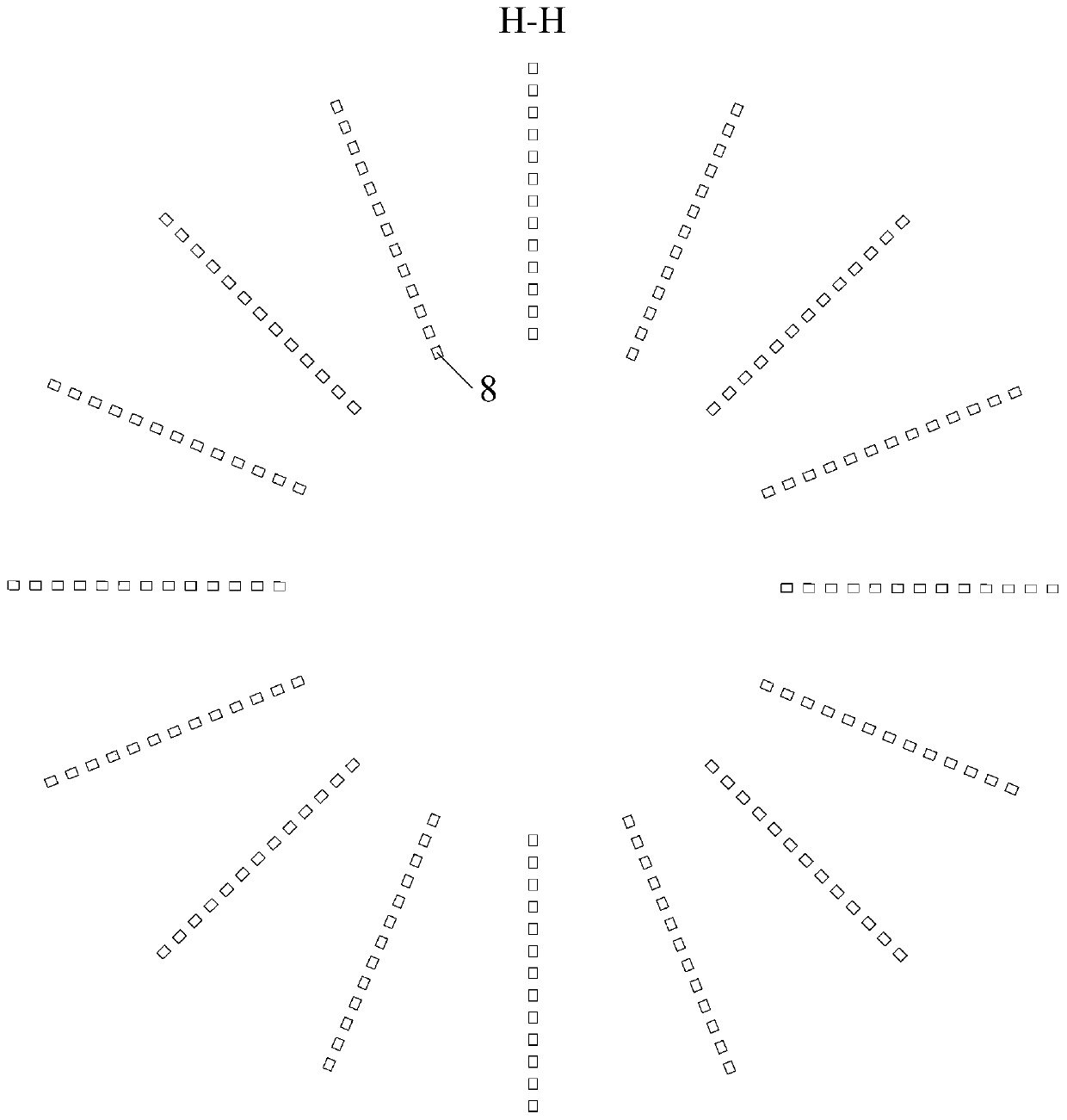
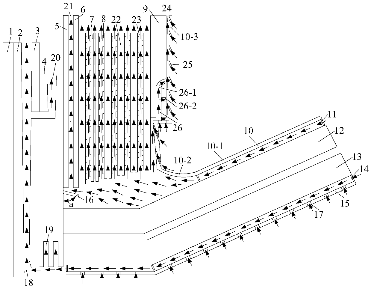
[0021] Specific implementation mode one: combine figure 1 and figure 2Describe this embodiment. The multi-shielding concave-convex surround internal cooling type turbogenerator end ventilation cooling system described in this embodiment includes the end iron core 1 of the second section of the stator, the iron core 1 at the outer end of the first section of the stator Core 2, iron core at the inner end of the first section of the stator 3, self-cooling tooth pressure plate 4, inner lamination ring 5, outer lamination ring 6, concave-convex surrounding magnetic shield 7, heat dissipation teeth 8, self-cooling shield pressure plate 9 , bow-shaped large copper shield 10, upper fixed bracket 11, stator lower end winding 12, stator upper end winding 13, lower fixed bracket 14, bent large copper shield 15, inclined small copper shield 16, bent large Supplementary ventilation channel 17 inside copper shield, radial ventilation groove 18 of iron core at the end of stator, heat dissi...

specific Embodiment approach 2

[0024] Specific implementation mode two: combination image 3 Describe this embodiment. The difference between this embodiment and Embodiment 1 is that the outlet area of ​​the iron core radial ventilation groove 18 at the stator end is doubled, which improves the access to the radial ventilation groove 18 of the iron core at the stator end. The flow and velocity of the cooling gas increase the surface heat dissipation coefficient of the first section of the outer end iron core 2 of the stator and the inner end iron core 3 of the first section of the stator, and further reduce the The temperature of the iron core 3 at the inner end of the first section. Other components and connections are the same as those in Embodiment 1.

specific Embodiment approach 3

[0025] Specific implementation mode three: combination Figure 4 This embodiment is described. The difference between this embodiment and Embodiment 1 is that cooling fins 27 are installed on the arcuate large copper shield 10, which increases the contact area between the cooling gas and the arcuate large copper shield 10, and improves the cooling gas take away. The heat capacity of the bow-shaped large copper shield 10 effectively reduces the temperature of the bow-shaped large copper shield 10 . Other components and connections are the same as those in Embodiment 1.


PUM

PropertyMeasurementUnit
Axial widthaaaaaaaaaa
Radial heightaaaaaaaaaa
Axial widthaaaaaaaaaa

Abstract

The invention discloses a concave-convex surrounding internal cooling type turbine generator end ventilation cooling system with multiple shields, and relates to the field of motors. The problem thatthe temperature of an end component of an existing steam turbine generator is high is solved. A self-cooling type tooth pressing plate is provided with a gradually-widened type ventilation channel anda heat dissipation groove. An inner-layer pressing ring is pressed on the self-cooling type tooth pressing plate; a ventilating duct is formed between the inner-layer pressing ring and an outer-layerpressing ring; a reinforced ventilating duct and a self-cooling ventilating duct are formed in a concave-convex surrounding type magnetic shield; heat dissipation teeth are mounted on the surface ofthe concave-convex surrounding type magnetic shield; a self-cooling type shielding pressing plate is provided with the cooling channel, an arch-shaped large copper shield is located just in front of the self-cooling type shielding pressing plate, the arch-shaped large copper shield is provided with a ventilation groove, a bent large copper shield is located under an upper-layer end winding of thestator, the bent large copper shield is provided with a supplementary ventilation channel, and the inclined small copper shield is located under the inner-layer pressing ring. The cooling effect of the end component of the steam turbine generator is enhanced, the structure is simple, and implementation is convenient.

Description

technical field [0001] The invention relates to a concave-convex surrounding internal cooling type steam turbine generator end ventilation cooling system with multiple shields, which belongs to the field of motors. Background technique [0002] The stator coil pitch of the steam turbine generator is large, and the number of coils in each phase belt is large, resulting in long stator coil ends, so that a strong rotating leakage magnetic field is formed at the end of the stator coil, and there will also be a magnetic field at the end of the rotor coil that follows the rotor Rotating leakage magnetic field, the two rotating leakage magnetic fields form a synthetic rotating leakage magnetic field at the end, in which the leakage magnetic field at the end of the stator coil is the main component. With the continuous increase of the single unit capacity of large turbogenerators, the line load of the generators gradually increases, which makes the current flowing through each stato...

Claims


Application Information

Patent Timeline
IPC IPC(8): H02K1/20
CPCH02K1/20
Inventor 韩继超王超徐骁王洋王磊戈宝军陶大军
Owner HARBIN UNIV OF SCI & TECH
Why Eureka
Try Eureka