Injection molding machine waste gas zero-emission system and process

An injection molding machine and zero-emission technology, applied in the separation of dispersed particles, chemical instruments and methods, separation methods, etc., can solve the problems of PE and PP waste, large air volume of fans, high efficiency of motors, etc., to reduce environmental pollution, reduce air volume, The effect of saving resources

Inactive Publication Date: 2020-06-05
山东海众化工科技有限公司
View PDF0 Cites 1 Cited by
  • Summary
  • Abstract
  • Description
  • Claims
  • Application Information

AI Technical Summary

Problems solved by technology

Although it passed the standard discharge, it caused a certain amount of environmental pollution, and caused waste of PE and PP that could have been reused
At the same time, in order to enhance the effect of air induction, the fan used has a large air volume and a high motor efficiency, which in turn consumes a lot of power

Method used


Image

  • Injection molding machine waste gas zero-emission system and process

Examples


Embodiment 1

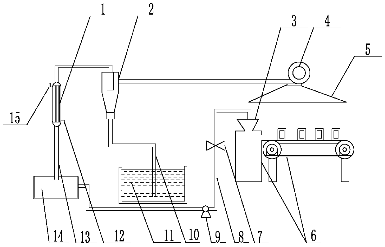
[0030] like figure 1 As shown, the described injection molding machine exhaust gas zero-emission system includes an injection molding machine 6, a draft hood 5 is arranged above the injection molding machine 6, the draft hood 5 is connected with the induced draft fan 4, and the induced draft fan 4 is connected with the cyclone separator 2, The top of the cyclone separator 2 is connected to the condenser 1, and the condenser 1 is connected to the raw material collection device 14 through the pipeline A13; the bottom of the cyclone separator 2 is connected to the heavy oil adsorption tank 11 through the pipeline B10.

[0031] The pipeline B10 extends into the bottom of the heavy oil adsorption tank 11, so that the heavy oil can better adsorb the exhaust gas that cannot be recycled.

[0032] The end of the condenser 1 close to the cyclone separator 2 is provided with a water outlet 15 , and the end of the condenser 1 close to the raw material collection device 14 is provided with...

Embodiment 2

[0035] Other structures are the same as those in Embodiment 1, except that:

[0036] The induced draft fan 4 is a low-power induced draft fan 4 .

[0037] The cyclone separator 2 is a high temperature cyclone separator 2 .

Embodiment 3

[0039] Other structures are the same as those in Embodiment 1, except that:

[0040] The raw material collecting device 14 is connected to the hopper 3 on the injection molding machine 6 through the pump 9, which not only prevents the exhaust gas from being discharged, but also realizes the recycling and reuse of the exhaust gas, which is energy-saving and environmentally friendly.

[0041] A one-way valve 7 is provided on the pipeline C8 connecting the raw material collecting device 14 with the hopper 3 .

[0042] The zero-emission system for injection molding machine exhaust gas according to the present invention is especially suitable for a space in a closed state. The waste gas such as PP and PE produced by the injection molding machine is collected by the induced draft hood 5 and the induced draft fan 4 and sucked into the cyclone separator 2. The cyclone separator 2 separates the inhaled gas into two parts, and one part is recyclable waste gas. The other part is waste g...


PUM


Abstract

The invention relates to an injection molding machine waste gas zero emission system and process, and belongs to the technical field of environmental protection. The zero emission system for the wastegas of the injection molding machine comprises the injection molding machine, an induced draft hood is arranged above the injection molding machine and connected with an induced draft fan, the induced draft fan is connected with a cyclone separator, the top of the cyclone separator is connected with a condenser, and the condenser is connected with a raw material collecting device through a pipeline A; the bottom of the cyclone separator is connected with the heavy oil adsorption tank through a pipeline B. The process comprises collecting waste gas generated by an injection molding machine andsucking the waste gas into a cyclone separator and separating the waste gas into two parts; wherein the recyclable waste gas is condensed into a viscous flow state material and then is collected; theorganic components in the waste gas, which cannot be recycled, by the heavy oil, and the adsorbed gas is discharged into an injection molding workshop. The system and process is scientific and reasonable in design and convenient to use, resources are saved, the production and treatment cost is reduced, environmental pollution is reduced, and energy conservation and environmental protection are achieved.

Description

technical field [0001] The invention relates to a zero-emission system and process for exhaust gas of an injection molding machine, and belongs to the technical field of environmental protection. Background technique [0002] In the plastic production process, waste gas such as PE and PP will be generated. The main parts of chemical waste gas are: hot melt system and blow molding system. The main components of waste gas are PE and PP waste gas produced by heating of polyethylene and polypropylene. [0003] The waste gas treatment in the traditional plastic production process is to collect the PE and PP waste gas generated by the heating of polyethylene and polypropylene through the gas collecting hood, enter the electrostatic purifier through the gas gathering pipeline, and treat the treated waste gas by low temperature plasma. exhaust gas exhaust pipe discharge. Although it is discharged up to the standard, it will cause a certain amount of environmental pollution, and ca...

Claims


Application Information

Patent Timeline
Patent Type & Authority Applications(China)
IPC IPC(8): B01D45/16B01D53/00B01D53/18B29C45/17
CPCB01D45/16B01D53/002B01D53/1487B01D53/18B29C45/17B29C2045/1784
Inventor 冯柏成王志杰徐瑞吉史乃迎张光玉杨洛生史华英
Owner 山东海众化工科技有限公司
Why Eureka
Try Eureka