
Array substrate and manufacturing method thereof

An array substrate and manufacturing method technology, applied in the display field, can solve problems such as metal electrostatic breakdown, product yield impact, molybdenum and titanium metal residue, etc., to achieve the effect of blocking copper diffusion, avoiding copper hollowing, and improving adhesion

Inactive Publication Date: 2020-06-05
TCL CHINA STAR OPTOELECTRONICS TECH CO LTD
View PDF5 Cites 4 Cited by
  • Summary
  • Abstract
  • Description
  • Claims
  • Application Information

AI Technical Summary

Problems solved by technology

In the process of using molybdenum metal as the double metal layer, because the copper / molybdenum structure is prone to double metal corrosion during the metal patterning process, the copper metal will be corroded during the subsequent photoresist stripping process, forming a copper hollowing phenomenon. The occurrence of copper hollowing will form metal tips, and different layers of metals are prone to electrostatic breakdown in the subsequent manufacturing process, which has a great impact on product yield
The use of molybdenum-titanium alloy as an additional metal layer can significantly improve the corrosion of copper metal, but due to the presence of titanium in molybdenum-titanium alloy, it is necessary to use a wet etching solution containing fluorine to etch in the metal patterning process, and the etching The rate is low, and the problem of molybdenum and titanium metal residues is prone to occur

Method used


Image

  • Array substrate and manufacturing method thereof
  • Array substrate and manufacturing method thereof
  • Array substrate and manufacturing method thereof

Examples


Embodiment Construction

[0027] The technical solutions in the embodiments of the present application will be clearly and completely described below in conjunction with the drawings in the embodiments of the present application. Apparently, the described embodiments are only some of the embodiments of this application, not all of them. Based on the embodiments in this application, all other embodiments obtained by those skilled in the art without making creative efforts belong to the scope of protection of this application.

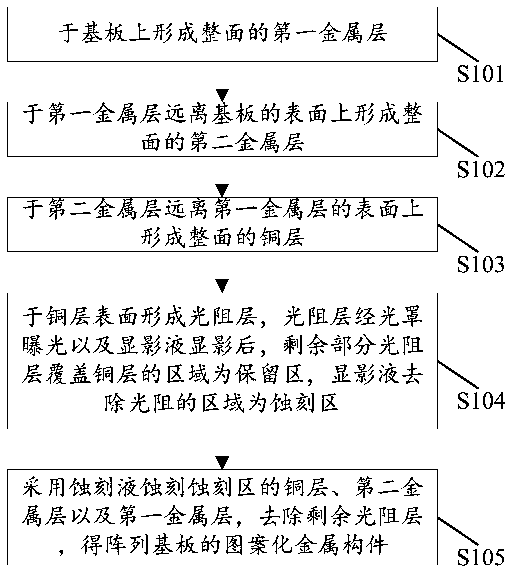
[0028] see figure 1 as well as figure 2 , figure 1 is a schematic structural diagram of the array substrate of the embodiment of the present application, figure 2 for figure 1 A schematic diagram of the structure of the source-drain electrodes in the array substrate shown. The array substrate 100 is a thin film transistor array substrate, and the array substrate 100 can be used in a liquid crystal display panel or an organic light emitting diode display panel. The array s...


PUM

PropertyMeasurementUnit
thicknessaaaaaaaaaa
thicknessaaaaaaaaaa
thicknessaaaaaaaaaa

Abstract

The invention provides an array substrate and a manufacturing method thereof. A patterned metal component of the array substrate comprises a patterned first metal layer, a patterned second metal layerand a patterned copper layer which are sequentially arranged on the substrate in a stacked mode, wherein the speed of etching the second metal layer by the etching solution is smaller than that of etching the first metal layer by the etching solution. The structures of the second metal layer and the first metal layer are patterned, the problem of metal residue during etching of the second metal layer can be avoided, the problem of copper hollowing caused by corrosion of the patterned second metal layer can be avoided, the adhesive force between the patterned first metal layer and the substrate is greater than that between the patterned copper layer and the substrate, the adhesive force of the patterned metal component on the substrate is improved, and copper diffusion can be prevented.

Description

technical field [0001] The present application relates to the field of display technology, in particular to an array substrate and a manufacturing method thereof. Background technique [0002] In high-generation liquid crystal panels, copper materials are used as metal wires because of their low impedance and strong resistance to electromigration, making it a trend to replace traditional aluminum materials. However, the adhesion between copper metal and glass is poor, metal peeling is easy to occur, and copper metal is easy to diffuse, which deteriorates the performance of thin film transistor (Thin Film Transistor, TFT) devices. Usually, a metal layer is added to improve the adhesion of the copper metal layer and prevent copper diffusion. In the manufacturing process of traditional display panels, molybdenum / titanium / molybdenum-titanium alloys are usually used for the added metal layer. In the process of using molybdenum metal as the double metal layer, because the copper / ...

Claims


Application Information

Patent Timeline
Patent Type & Authority Applications(China)
IPC IPC(8): H01L21/77H01L27/12
CPCH01L27/1244H01L27/1259H01L27/124H01L27/1222H01L27/127
Inventor 陈梦
Owner TCL CHINA STAR OPTOELECTRONICS TECH CO LTD
Learn More