A bus capacitor active discharge circuit
A bus capacitor and discharge circuit technology, applied in the electric drive field of new energy vehicles, can solve problems such as high cost requirements of discharge resistors, and achieve the effects of reducing the risk of failure, reducing current overshoot, and ensuring service life
- Summary
- Abstract
- Description
- Claims
- Application Information
AI Technical Summary
Problems solved by technology
Method used
Image
Examples
Embodiment
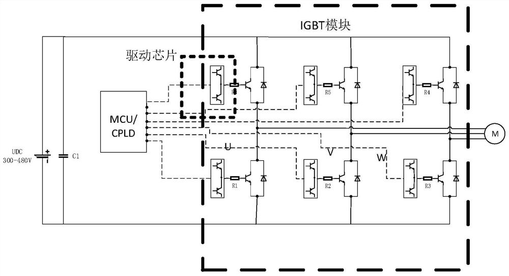
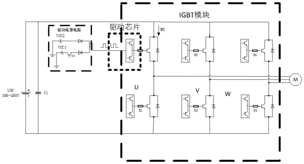
[0025] Embodiment: This application provides a bus capacitor active discharge circuit, combined with reference figure 2 and image 3 , the bus capacitor active discharge circuit includes: a DC power supply UDC, a bus capacitor C1, a drive power circuit, a control circuit, an IGBT module, and a motor controller M.
[0026] The bus capacitor C1 is connected to the positive and negative DC bus between the DC power supply UDC and the IGBT module; the IGBT module includes a driver chip, a gate resistor and an inverter.
[0027] Each switching device in the inverter includes an insulated gate bipolar transistor IGBT or other power semiconductor switching devices, and each IGBT includes a reverse blocking diode; each IGBT in the inverter corresponds to a group of driver chips and gate resistors, The output end of the drive chip is connected to the gate of the IGBT through the gate resistor; the control circuit is connected to each drive chip; the output end of the drive power circu...
PUM
 Abstract
Description
Claims
Application Information
 - R&D
- Intellectual Property
- Life Sciences
- Materials
- Tech Scout
- Unparalleled Data Quality
- Higher Quality Content
- 60% Fewer Hallucinations
Browse by: Latest US Patents, China's latest patents, Technical Efficacy Thesaurus, Application Domain, Technology Topic, Popular Technical Reports.
© 2025 PatSnap. All rights reserved.Legal|Privacy policy|Modern Slavery Act Transparency Statement|Sitemap|About US| Contact US: help@patsnap.com


