Laser microdissection apparatus and method

A laser micro-cutting and cutting curve technology, applied in laser welding equipment, metal processing equipment, welding equipment, etc., can solve the problem that the corresponding relationship between the cutting curve and the action of the micro-mirror array group has not been established, and the aberration of the micro-mirror array group increases. , chromatic aberration, inability to achieve cutting and other problems, to achieve the effect of small error, reduced volume, and short time consumption

Active Publication Date: 2022-02-22
NINGBO UNIV +1
View PDF10 Cites 0 Cited by
  • Summary
  • Abstract
  • Description
  • Claims
  • Application Information

AI Technical Summary

Problems solved by technology

[0009] 1. The cutting of any curve cannot be realized, that is, the corresponding relationship between the cutting curve and the action of the micromirror array group has not been established;
[0010] 2. The micromirror array group adjusts the direction of the output light, and combines with the objective lens to converge the cutting light on the cutting object, and then uses the angle adjustment of the micromirror array to change the direction of the output light, so that the converging point of the cutting light sweeps over the cutting object At different positions corresponding to the cutting curve, it takes a long time, troublesome manipulation, and large errors;
[0011] 3. The application of the micromirror array group increases errors such as aberration and chromatic aberration;

Method used


Image

  • Laser microdissection apparatus and method
  • Laser microdissection apparatus and method
  • Laser microdissection apparatus and method

Examples


Embodiment 1

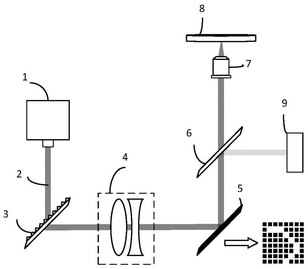
[0044] figure 1 Schematically provides a schematic structural diagram of the laser microdissection device in Example 1 of the present invention, as figure 1 As shown, the laser microdissection device includes:

[0045] Laser 1 and objective lens, these devices are the prior art in this field, and specific structure and mode of operation are not repeated here;

[0046] Micromirror array group 5, the micromirror array group includes a plurality of micromirrors arranged in an array; the output light of the laser is directed to the objective lens after being reflected by the micromirror array group;

[0047] A drawing unit, the drawing unit is suitable for operators to draw cutting curves, such as drawing cutting curves on computer screens and portable terminals;

[0048] A calculation unit, the calculation unit obtains the inclination angle of each micromirror in the micromirror array group relative to the output light corresponding to any point in the cutting curve according t...

Embodiment 2

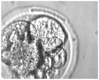
[0087] An application example of the laser microdissection device and method according to Embodiment 1 of the invention in embryo cutting.

[0088] In this application example, if figure 1 As shown, a laser 1, a transmission grating 3, an achromatic lens group 4, a micromirror array group 5, a dichromatic mirror 6, an objective lens 7, and a petri dish 8 are sequentially arranged on the optical path, and an eyepiece and a camera 9 are arranged on the side of the dichromatic mirror 6; The output light 2 of the laser 1 passes through the transmission grating 3 and the lens group 4, reflects on the micromirror array group 5, and passes through the dichromatic mirror 6 and the objective lens 7; the drawing unit and the calculation unit adopt a computer, which is suitable for the operator to operate on the computer Draw the cutting curve and display it on the computer screen;

[0089] In the laser microdissection method of the embodiment of the present invention, the laser microdi...


PUM


Abstract

The invention provides a laser microdissection device and method, the laser microdissection device includes a laser and an objective lens; the micromirror array group includes a plurality of microreflectors arranged in an array; the output light of the laser passes through the The reflection of the micromirror array group is directed to the objective lens; the drawing unit is suitable for the operator to draw a cutting curve; the calculation unit obtains each of the micromirror array groups corresponding to any point in the cutting curve according to the drawn cutting curve The inclination angles of the micro-mirrors relative to the output light are transmitted to the control unit; the control unit adjusts each micro-mirror according to the received inclination angles. The invention has the advantages of simple structure, accurate cutting and the like.

Description

technical field [0001] The invention relates to the field of biology, in particular to a laser microdissection device and method. Background technique [0002] At present, laser microdissection generally adopts the following two methods: [0003] 1. DMD realizes closed cutting curve, DMD adjustment angle is consistent, please refer to Chinese patent CN107186364A; the disadvantage of this solution is: [0004] Only parallel light can be reflected, and only one point can be obtained through the objective lens, which is not a curve; at the same time, errors such as aberrations generated after the optical path passes through the objective lens are not considered. [0005] 2. Use the transmission components to move the light source or scan the galvanometer to change the direction of light travel. The disadvantages of this scheme are: [0006] The transmission components are bulky, with low precision and high energy consumption. [0007] At present, there is a micromirror arra...

Claims


Application Information

Patent Timeline
Patent Type & Authority Patents(China)
IPC IPC(8): B23K26/38B23K26/70
CPCB23K26/38B23K26/70B23K26/702
Inventor 闻路红刘云洪欢欢胡舜迪蔡雨杏郭荣张宏凯邱如标
Owner NINGBO UNIV
Why Eureka
Try Eureka