
Design method of Fermat spiral Greek ladder photon sieve and imaging light path thereof

An imaging optical path and photon sieve technology, applied in optics, diffraction gratings, optical elements, etc., to achieve the effect of improving the beam imaging quality and increasing the imaging contrast

Active Publication Date: 2020-06-16
SHANGHAI INST OF OPTICS & FINE MECHANICS CHINESE ACAD OF SCI
View PDF11 Cites 6 Cited by
  • Summary
  • Abstract
  • Description
  • Claims
  • Application Information

AI Technical Summary

Problems solved by technology

Therefore, zone plates and photon sieves can only achieve one imaging result

Method used


Image

  • Design method of Fermat spiral Greek ladder photon sieve and imaging light path thereof
  • Design method of Fermat spiral Greek ladder photon sieve and imaging light path thereof
  • Design method of Fermat spiral Greek ladder photon sieve and imaging light path thereof

Examples


Embodiment 1

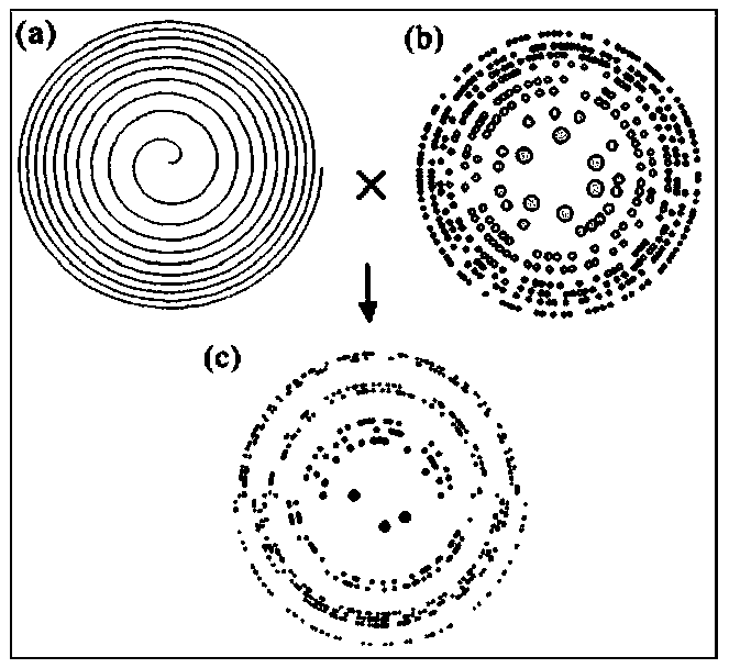
[0025] figure 1 A schematic diagram of the design process of a Fermat spiral Greek ladder photon sieve. In the picture:

[0026] (a) is a Fermat spiral diagram. The Fermat spiral conforms to the equation R=a×θ 1 / 2 , where R is the radius in polarized coordinates, a is the adjustment coefficient, and θ is the angle in polarized coordinates. When the radial phase of the Greek ladder photon sieve changes 2π, the Fermat helix rotates one circle.

[0027] (b) is a schematic diagram of the structure of the Greek ladder photonic sieve, which is obtained by modulating the pore distribution in the photonic sieve with the Greek ladder sequence code. Under monochromatic parallel wave illumination, a three-dimensional array focal point with equal intensity distribution can be generated to achieve coherent focusing and imaging. The overall radius and wavelength focal length of the Greek ladder photon sieve follow the following relationship: r n 2 =n×λ×f, where n represents the numbe...

Embodiment 2

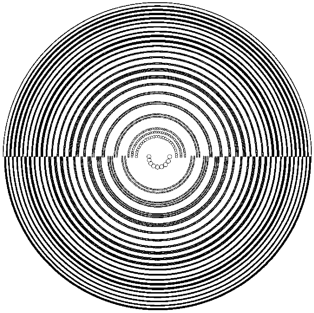
[0043] According to the relationship between the overall radius of the Fermat spiral Greek ladder photon sieve and the wavelength focal length: r n 2 =n×λ×f, when the wavelength and the reference focal length are respectively set to 2.8nm and 2.8mm, a Greek ladder photon sieve working in the X-ray band is obtained. The Fermat spiral Greek ladder photon sieve can be obtained through the modulation of the Fermat spiral as mentioned above, which can produce axial three focal points. The focal lengths of the three focal points are: 3.3799mm, 2.8000mm, and 2.3899mm respectively. The processed base is the amplitude Type, making the amplitude type Fermat spiral Greek ladder photon sieve, the amplitude type Fermat spiral Greek ladder photon sieve uses diffraction to realize the modulation of the amplitude and phase of the light wavefront, and will not lose its effect due to the strong absorption characteristics of the material. Repeat the design process and imaging optical path in Ex...


PUM


Abstract

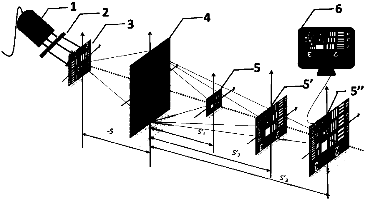
A point spread function determines an imaging property of an optical system, and different imaging results can be realized by different point spread functions. A Fermat spiral line is introduced intothe Greek ladder photon sieve, and the Fermat spiral line modulates distribution positions of sieve holes in the Greek ladder photon sieve to obtain the Fermat spiral Greek ladder photon sieve. A plurality of axial focuses are generated through the imaging light path based on the Fermat spiral Greek ladder photon sieve, a function of a multi-focal-plane different-point spread function of a singledevice is achieved, anisotropic Airy disks and vortex focuses are included, and the method can be applied to focusing and imaging from X rays to a terahertz waveband in a coherent light field. A first focus and a third focus are anisotropic Airy disks, different resolutions in different directions can be achieved for an input object, and the resolution of the object in the interested direction can be improved; the second focus is the vortex focus, the vortex focus can be used for optical capture; in addition, radial Hilbert transform can be achieved based on spiral phase filtering when the vortex focus is used for imaging, and edge enhancement of an amplitude and a phase object is realized.

Description

technical field [0001] The invention relates to a diffractive optical element, in particular to a design method of a Fermat spiral Greek ladder photon sieve capable of realizing different point spread functions of multiple focal planes under a coherent light field and its imaging optical path. Background technique [0002] Due to its strong penetrating ability, X-rays are widely used in the non-destructive imaging and detection of internal structures in biomedical imaging, industrial production, material science and other fields. However, due to the strong absorption and weak refraction effect of the optical device material in the visible light band, the visible light band device cannot be used in the short wavelength band. As a diffractive optical element, the photon sieve can realize focusing and imaging in the X-ray band by modulating the amplitude and phase of the light wavefront. The photon sieve is developed on the basis of the Fresnel zone plate. In addition to the p...

Claims


Application Information

Patent Timeline
IPC IPC(8): G02B5/18G02B27/00G02B27/42
CPCG02B5/1876G02B27/0012G02B27/4205
Inventor 张军勇徐守英周申蕾朱健强张艳丽
Owner SHANGHAI INST OF OPTICS & FINE MECHANICS CHINESE ACAD OF SCI
Learn More