
Tunable, high-resolution and multi-band enhanced plasma generating device

A plasma, high-resolution technology, applied in plasma, antenna support/installation device, complex mathematical operations, etc., can solve the problems of low transmission efficiency, poor bandpass frequency characteristics of single-layer plasma enhancement device, etc The effect of wide application prospects

Active Publication Date: 2020-06-16
HARBIN INST OF TECH
View PDF12 Cites 5 Cited by
  • Summary
  • Abstract
  • Description
  • Claims
  • Application Information

AI Technical Summary

Problems solved by technology

[0010] The present invention is to solve the problem that the existing multi-band signal transmission device has low transmission efficiency, needs to be used with a signal amplifier, and the band-pass frequency characteristic of the single-layer plasma enhancement device is poor

Method used


Image

  • Tunable, high-resolution and multi-band enhanced plasma generating device
  • Tunable, high-resolution and multi-band enhanced plasma generating device
  • Tunable, high-resolution and multi-band enhanced plasma generating device

Examples


Embodiment 1

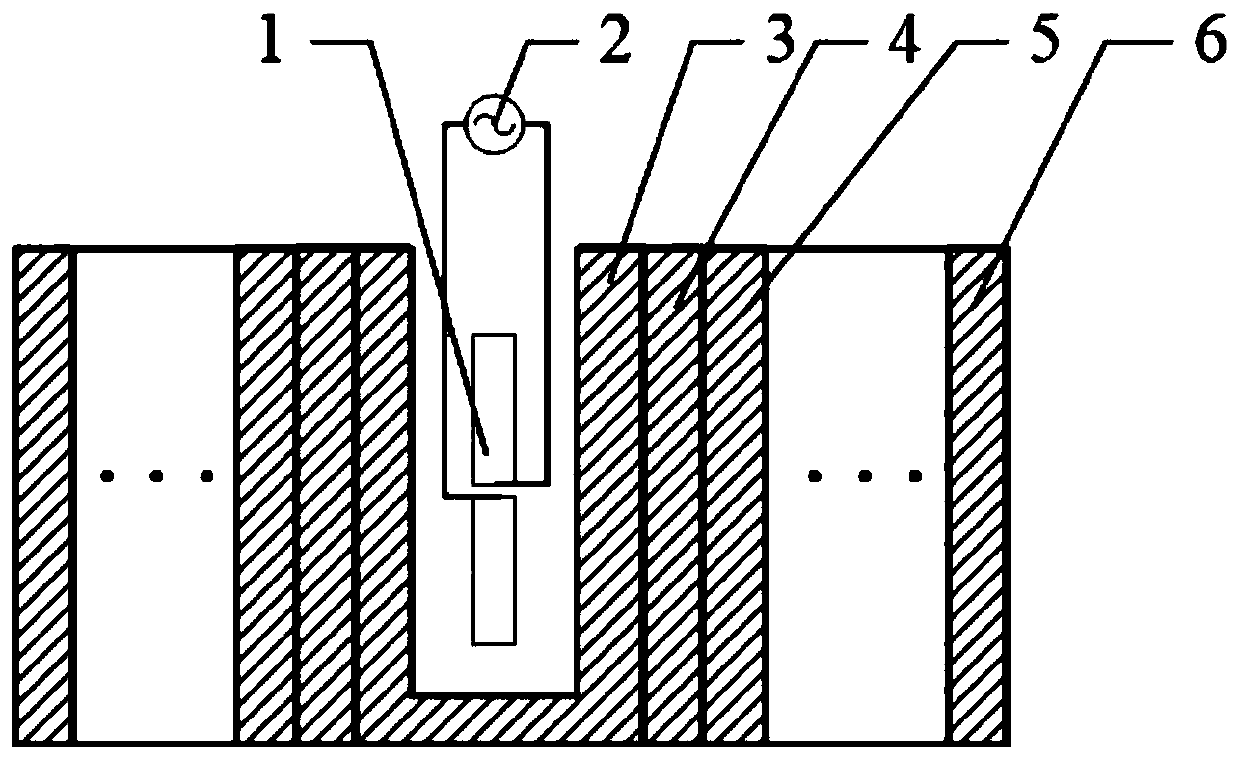
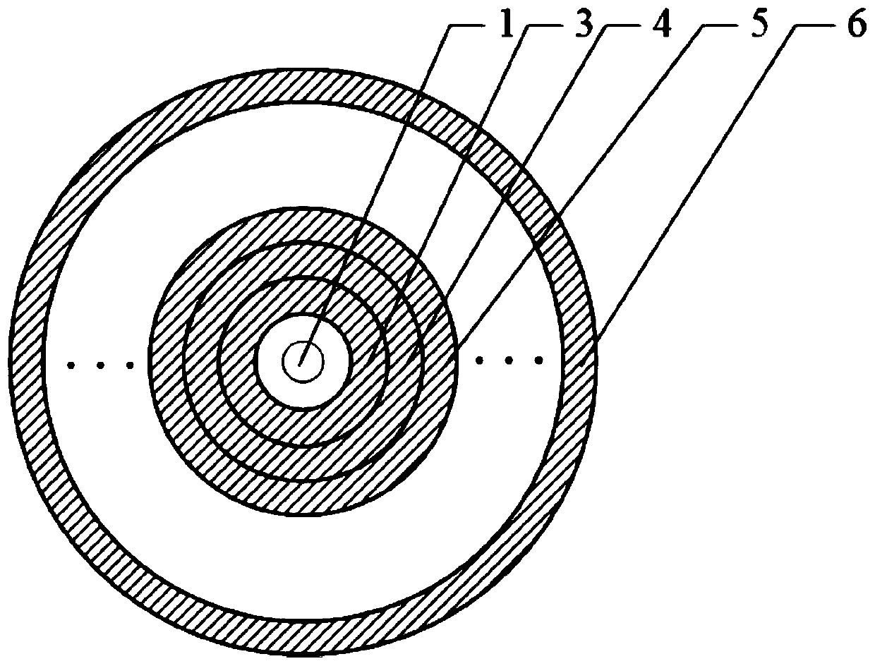
[0042] A tunable, high-resolution, multi-band enhanced plasma generator, including three plasma hoods and an antenna system;

[0043] The 3 plasma shields include No. 1 plasma shield to No. 3 plasma shield,

[0044] No. 1 plasma cover to No. 3 plasma cover are nested coaxially from the inside to the outside without gaps, the antenna system is located in the cover of the No. 1 plasma cover, and the antenna system is tightly covered by the No. 1 plasma cover;

[0045] The antenna system includes a dipole antenna 1 and a feeder 2,

[0046] Feeder 2 is used to power dipole antenna 1,

[0047] Dipole antenna 1, used to transmit electromagnetic wave signals in the target band,

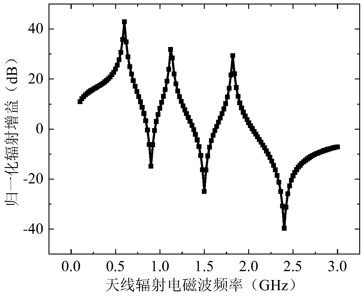
[0048] Each plasma cover is used to enhance the intensity of the target waveband electromagnetic wave signal emitted by the dipole antenna 1, or extract and enhance the target waveband electromagnetic wave signal from the background electromagnetic field, where the range of enhancement is the range emitted by N plasma ...

Embodiment 2

[0054] A tunable, high-resolution, multi-band enhanced plasma generator, including three plasma hoods and an antenna system;

[0055] The 3 plasma shields include No. 1 plasma shield to No. 3 plasma shield,

[0056] No. 1 plasma cover to No. 3 plasma cover are nested coaxially from the inside to the outside without gaps, the antenna system is located in the cover of the No. 1 plasma cover, and the antenna system is tightly covered by the No. 1 plasma cover;

[0057] The antenna system includes a dipole antenna 1 and a feeder 2,

[0058] Feeder 2 is used to power dipole antenna 1,

[0059] Dipole antenna 1, used to transmit electromagnetic wave signals in the target band,

[0060] Each plasma cover is used to enhance the intensity of the target waveband electromagnetic wave signal emitted by the dipole antenna 1, or extract and enhance the target waveband electromagnetic wave signal from the background electromagnetic field, where the range of enhancement is the range emitted by N plasma ...


PUM


Abstract

The invention discloses a tunable, high-resolution and multi-band enhanced plasma generating device, and relates to the technical field of low-temperature plasma application. The invention aims to solve the problems that an existing multi-band signal transmission device is low in transmission efficiency and needs to be used in cooperation with a signal amplifier, and a single-layer plasma enhancement device is poor in band-pass frequency characteristic. N plasma covers are coaxially nested, and the N plasma covers are sequentially a first plasma cover, a second plasma cover to an N plasma cover from inside to outside; an antenna system is located in the cover of the first plasma cover; a dipole antenna is used for emitting a plurality of target waveband electromagnetic waves or receiving target waveband electromagnetic waves input by the background electromagnetic field through the N plasma covers; each plasma cover enhances the intensity of the target waveband electromagnetic wave signals emitted by the dipole antenna or extracts and enhances the target waveband electromagnetic wave signals from the background electromagnetic field, and the enhancement range is that the logarithmic gain of the power of the signals emitted by the N plasma covers is greater than or equal to 10dB. The device disclosed by the invention is used for enhancing signals.

Description

Technical field [0001] The invention relates to a plasma device. It belongs to the application technical field of low-temperature plasma. Background technique [0002] With the development of modern microwave communication technology, in order to make full use of cable bandwidth resources, wavelength division multiplexing is usually used to increase transmission capacity. Among them, a wavelength division multiplexer is used at the signal sending end to combine carriers of different wavelengths for transmission, and a demultiplexer (equivalent optical bandpass filter) is used at the signal receiving end to separate each signal. In order to ensure the quality of communication, multiplexers and demultiplexers need to have the characteristics of low in-band insertion loss, obvious separation isolation, and high stability of the center wavelength. In addition, in the context of complex electromagnetic environment operations in modern military warfare, the enemy and ourselves often ...

Claims


Application Information

Patent Timeline
Patent Type & Authority Applications(China)
IPC IPC(8): H01Q1/22H05H1/24G06F17/11
CPCG06F17/11H01Q1/22H05H1/24
Inventor 聂秋月陈培奇张仲麟
Owner HARBIN INST OF TECH
Learn More