A packaging device for silicon microphone chips

A technology for packaging equipment and silicon microphones, applied in sensors, electrostatic transducers, microphones, electrical components, etc., can solve the problems of increasing product error rate, low production efficiency, and mismatching production efficiency, reducing labor intensity, The effect of reducing site waste and compact installation

Active Publication Date: 2021-05-28
SHENZHEN DINGJING TECH CO LTD
View PDF10 Cites 0 Cited by
  • Summary
  • Abstract
  • Description
  • Claims
  • Application Information

AI Technical Summary

Problems solved by technology

However, this method is costly, wastes space, increases the error rate of products, and because the production efficiency of each production equipment in the corresponding process does not match, the overall production efficiency is not high.

Method used


Image

  • A packaging device for silicon microphone chips
  • A packaging device for silicon microphone chips
  • A packaging device for silicon microphone chips

Examples


Embodiment 1

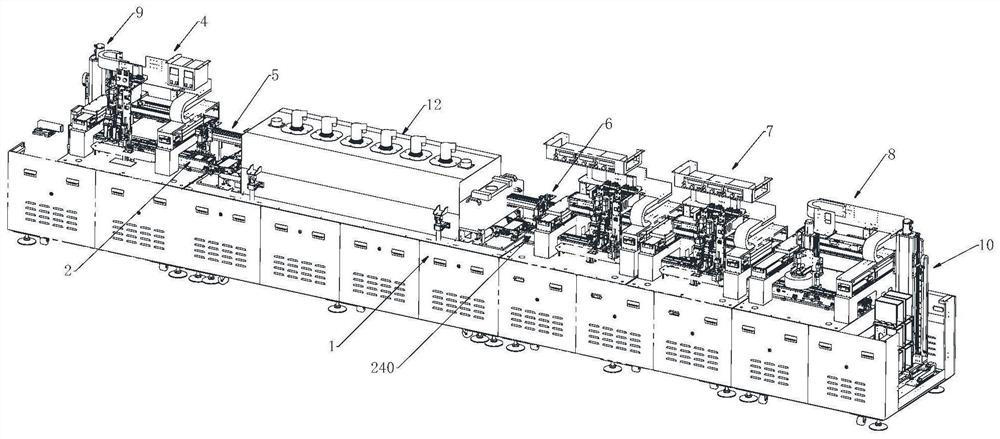
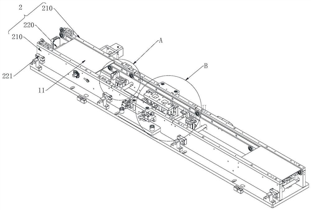
[0049] The packaging equipment for silicon microphone chips of the present invention includes a workbench 1, a first flow channel 2 and a second flow channel 240 are arranged side by side on the upper end of the workbench 1, and a drying oven is arranged between the first flow channel 2 and the second flow channel 240. The baking device 12, the workbench 1 is provided with a feeding device 9, a dispensing device 4 and a first manipulator 5 located above the first flow channel 2 and arranged in sequence along the conveying direction of the first flow channel 2, and the workbench 1 is also provided with a The second manipulator 6, the tin drawing device 7, the AOI detection device 8 and the unloading device 10 arranged in sequence above the second flow channel 240 along the conveying direction of the second flow channel 240; the first flow channel 2 and the second flow channel 240 both include The connecting column 220 and the two limiting plates 210 arranged side by side, the tw...

Embodiment 2

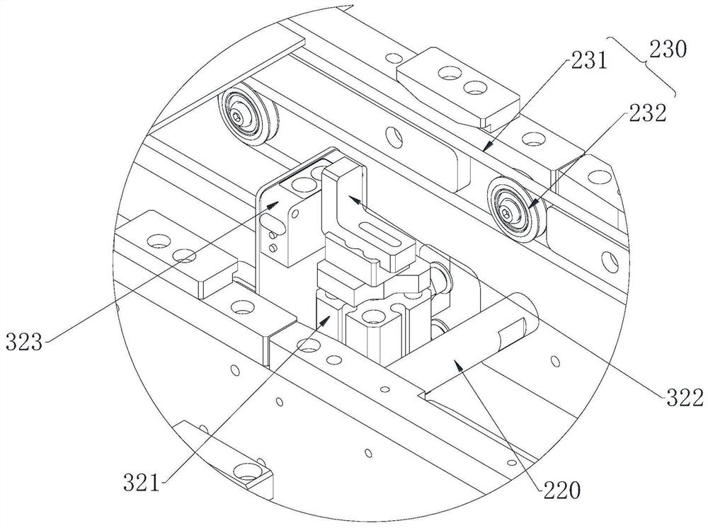
[0052] The present embodiment is further optimized on the basis of Embodiment 1 as follows: the belt assembly 230 includes a belt 231, a pulley 232 and a drive motor, a plurality of pulleys 232 are rotationally connected with the inner sidewall of the limiting plate 210, and the belt 231 is sleeved on On the periphery of all the pulleys 232 on the same side, the drive shaft of the drive motor passes through the limiting plate 210 and is connected to the pulleys 232 with each other.

[0053] After adopting the above-mentioned technical solution: the two limiting plates 210 are vertically arranged, and the two limiting plates 210 are fixedly connected through the connecting column 220, and a space for accommodating the movement of the chip is formed between the two limiting plates 210, and the two limiting plates 210 are connected vertically. A belt assembly 230 is arranged on the opposite inner side of the limiting plate 210. The belt assembly 230 is divided into two groups. The...

Embodiment 3

[0055]This embodiment is further optimized on the basis of Embodiment 1 as follows: the clamping unit 310 includes a horizontal bottom plate 311, a push plate 315, a load-bearing platform 313, a push-pull cylinder 312 and a first jacking cylinder 314, the horizontal The bottom plate 311 is located at the upper end of the workbench 1, the first jacking cylinder 314 is arranged on the upper end of the horizontal bottom plate 311, the upper end of the first jacking cylinder 314 is connected to the load-bearing platform 313, and the horizontal bottom plate 311 is also provided with a plurality of Horizontal adjustment bolt 316, the push-pull cylinder 312 is connected with the outer side wall of the limit plate 210, the push-pull cylinder 312 is connected with the push plate 315 after penetrating the limit plate 210, and the push plate 315 is located on the outside of the belt assembly 230 . The limiting assembly 320 includes a stopper 322 and a second jacking cylinder 321, the sec...


PUM


Abstract

The invention discloses a packaging device for a silicon microphone chip, each station is compactly installed, reduces the waste of site space, does not need to be manually transferred between each station, reduces labor intensity, and improves the overall production of the production line efficiency. The upper end of the workbench of the present invention is provided with a first runner and a second runner side by side, a baking device is arranged between the first runner and the second runner, and the workbench is provided with a feeding device, a glue dispensing device and a first manipulator, The workbench is also equipped with a second manipulator, tin drawing device, AOI detection device and unloading device; both the first flow channel and the second flow channel include connecting columns and two limit plates arranged side by side, and the inner sides of the two limit plates The wall is provided with a belt assembly, the upper ends of the two belt assemblies are provided with a carriage, the glue dispensing device and the tin painting device are provided below a clamping unit, and the front and rear sides of the clamping unit are respectively provided with limit assemblies.

Description

technical field [0001] The invention relates to the technical field of silicon microphone production and processing equipment, in particular to packaging equipment for silicon microphone chips. Background technique [0002] Silicon microphone, also known as miniature silicon-based microphone, is a miniature microphone, only half the size of ordinary microphones, but has the same acoustic and electrical performance as ordinary microphones, and is more durable, more heat-resistant, and lower power consumption . The silicon microphone contains two chips, namely a MEMS chip and an ASIC chip, and the two chips are packaged on a surface-mounted packaging carrier through a silicon-based MEMS process. [0003] But the current preparation of silicon microphone chips cannot really achieve mass production. To achieve mass production, suppliers must not only quickly expand production capacity, but also be able to provide products with low cost, high reliability, and excellent acoustic...

Claims


Application Information

Patent Timeline
Patent Type & Authority Patents(China)
IPC IPC(8): H04R31/00H04R19/04H04R19/00
CPCH04R19/005H04R19/04H04R31/00H04R2201/003
Inventor 喻泷
Owner SHENZHEN DINGJING TECH CO LTD
Why Eureka
Try Eureka