A liquid level adjustment mechanism and transfer coating machine
A liquid level adjustment and baffle adjustment technology, which is applied to the surface coating device, coating, electrode collector coating, etc., can solve the problems of pressure change, cumbersome operation, and poor fluidity, and achieve The surface density of the pole piece is stable, the surface density of the pole piece is guaranteed, and the effect of improving product quality
- Summary
- Abstract
- Description
- Claims
- Application Information
AI Technical Summary
Problems solved by technology
Method used
Image
Examples
Embodiment 1
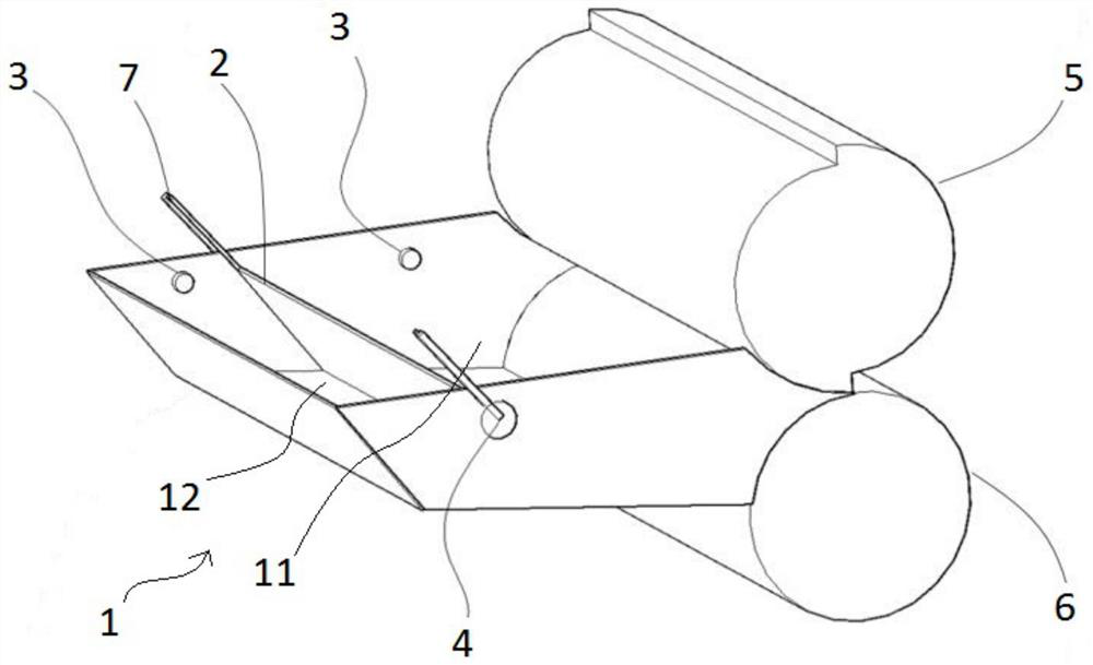
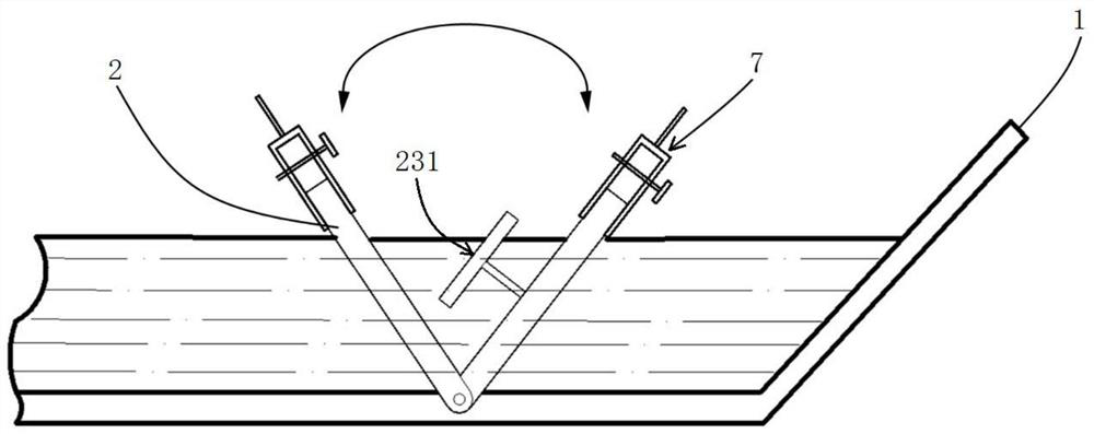
[0034] This embodiment provides a liquid level adjustment mechanism, such as figure 1 As shown, the liquid level adjustment mechanism mainly includes a trough 1 and an adjusting baffle 2, and the adjusting baffle 2 is rotatably arranged in the trough 1 to divide the trough 1 into a first trough 11 and a second trough with a variable volume. 12. The first trough 11 is close to the joint surface of the scraper roller 5 and the coating roller 6. The slurry contained in the first trough 11 is used to directly coat the battery current collector, and the slurry contained in the second trough 12 is The material is used to replenish the first material tank 11 with slurry, and the adjusting baffle 2 is configured to be able to adjust the liquid level in the first material tank 11 so as to maintain it at a preset liquid level.
[0035] The liquid level adjustment mechanism provided in this embodiment realizes the adjustment of the liquid level height of the slurry in the first material ...
Embodiment 2
[0045] This embodiment provides a liquid level adjustment mechanism, which differs from the liquid level adjustment mechanism in Embodiment 1 in that:
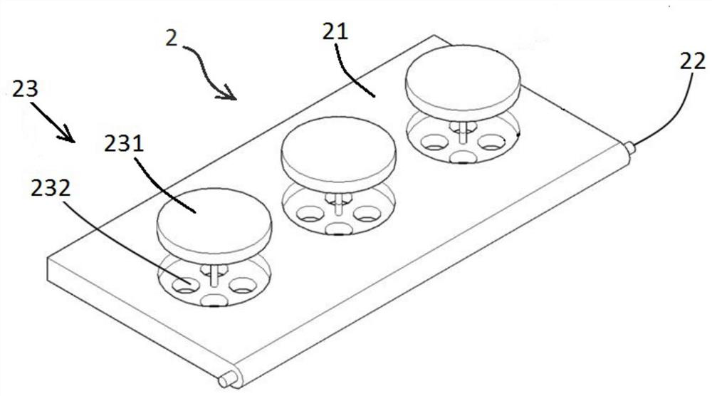
[0046] Such as figure 2 As shown, the regulating baffle 2 in this embodiment also includes a one-way valve assembly 23 arranged on the body 21, and the one-way valve assembly 23 is configured to be able to conduct or block the first material tank 11 and the second material tank 12 . In this embodiment, the battery slurry can flow between the first tank 11 and the second tank 12 through the one-way valve assembly 23 .
[0047] Specifically, the one-way valve assembly 23 includes a valve plate 231 and a flow hole 232. The flow hole 232 is opened on the body 21. The valve plate 231 is slidably connected to the body 21 and can open or block the flow hole 232 to realize the flow of the slurry. flow or block. The shape of the valve plate 231 and the number of flow holes 232 need to be designed according to actual needs. Optional...
Embodiment 3
[0055] This embodiment provides a transfer coating machine, which includes a scraper roller 5, a coating roller 6, and the liquid level adjustment mechanism of the first or second embodiment above. The scraper roller 5 and the coating roller 6 are connected on the frame, and the liquid level adjustment mechanism is arranged at the joint surface of the scraper roller 5 and the coating roller 6, and the rotation directions of the scraper roller 5 and the coating roller 6 are opposite, and the coating roller 6 The rotation makes the slurry in the trough 1 stick to the coating roller 6, scraped by the scraper roller 5, and then coated on the battery current collector to realize the coating of the battery current collector. The transfer type coating machine can improve the coating effect, and the surface density of the prepared electrode sheet is stable, and the product quality is high.
PUM
 Abstract
Description
Claims
Application Information
 - R&D
- Intellectual Property
- Life Sciences
- Materials
- Tech Scout
- Unparalleled Data Quality
- Higher Quality Content
- 60% Fewer Hallucinations
Browse by: Latest US Patents, China's latest patents, Technical Efficacy Thesaurus, Application Domain, Technology Topic, Popular Technical Reports.
© 2025 PatSnap. All rights reserved.Legal|Privacy policy|Modern Slavery Act Transparency Statement|Sitemap|About US| Contact US: help@patsnap.com


