Spatial frequency identification method based on two-dimensional variational mode decomposition of machined surface

A technology of variational mode decomposition and surface processing, which is applied in character and pattern recognition, special data processing applications, complex mathematical operations, etc., and can solve large reconstruction errors, modal mixing, and unsatisfactory spatial frequency separation effects, etc. problem, to achieve the effect of solving incomplete decomposition and solving modal aliasing

Active Publication Date: 2020-06-19
INST OF MACHINERY MFG TECH CHINA ACAD OF ENG PHYSICS
View PDF6 Cites 0 Cited by
  • Summary
  • Abstract
  • Description
  • Claims
  • Application Information

AI Technical Summary

Problems solved by technology

[0004] The technical problem to be solved by the present invention is: the existing ultra-precision machining surface spatial frequency decomposition and identification method has the defects of modal aliasing and large reconstruction error, which leads to the inability to obtain better separation of the processed surface spatial frequency and may lead to decomposition The resulting data is distorted on the original data
The present invention provides a spatial frequency identification method based on two-dimensional variational mode decomposition of ultra-precision machining surface topography to solve the above problems, which effectively solves the problem of unsatisfactory spatial frequency separation caused by serious mode mixing in the existing method. Large structural errors lead to problems such as distortion of the original signal

Method used


Image

  • Spatial frequency identification method based on two-dimensional variational mode decomposition of machined surface
  • Spatial frequency identification method based on two-dimensional variational mode decomposition of machined surface
  • Spatial frequency identification method based on two-dimensional variational mode decomposition of machined surface

Examples


Embodiment 1

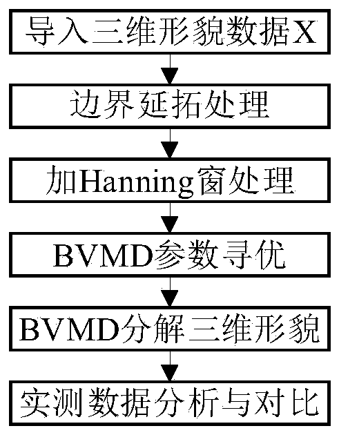
[0070] This embodiment provides a spatial frequency identification method based on two-dimensional variational mode decomposition of ultra-precision machining surface topography, and the specific steps are as follows:

[0071] Step 1, convert the collected 3D topography data into a matrix form, and determine the size of the matrix. The initial 3D topography is as follows Figure 4 shown.

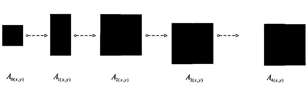
[0072] Step 2, gradually extend the matrix data in step 1, the schematic diagram of the extension is as follows image 3 As shown, the 3D shape data after continuation are as follows: Figure 5 Shown:

[0073] Step 21, record the workpiece surface shape data after ultra-precision machining as A 0(x,y) , where x, y are the sampling points of the row and column of the workpiece surface shape data after ultra-precision machining, (x=1,2,3,...,M; y=1,2,3,...,N) ;

[0074] Step 22, for A 0(x,y) Take its lower boundary as the axis, perform mirror flip, and compare the flipped data with A 0...


PUM


Abstract

The invention discloses a spatial frequency identification method based on two-dimensional variational mode decomposition of a machined surface. The method comprises the following steps of: preprocessing acquired three-dimensional topography data by utilizing mirror image continuation and a self-convolution Hanning window; then, a two-dimensional variational mode decomposition method is adopted todecompose the surface topography spatial frequency error; in addition, optimization is carried out by adopting a particle swarm annealing optimization algorithm aiming at two parameter penalty factors alpha and a decomposition layer number K which have the maximum influence on a decomposition result in the BVMD; through analysis of an actual machining surface, discrete wavelet decomposition and aBEMD algorithm are compared, modal aliasing serves as an index, and the advantages and applicability of the algorithm are verified. The invention provides a spatial frequency identification method based on ultra-precision machining surface topography two-dimensional variational mode decomposition. The problems of modal aliasing and large reconstruction errors existing in an existing decompositionmethod are solved, and the problems that ultra-precision machining surface space frequency decomposition is not thorough, and signal distortion is generated due to decomposition are effectively solved.

Description

technical field [0001] The present invention relates to the field of ultra-precision machining, in particular to a spatial frequency identification method based on two-dimensional variational mode decomposition of a machined surface. Background technique [0002] Ultra-precision machining is the main means of processing optical components. Taking single-point diamond fly-cutting machining as an example, factors such as machine tool spindle swing, tool vibration, hydraulic and air flotation system pressure fluctuations, and environmental disturbances will cause different spatial frequency bands on the surface of the workpiece to be machined. Appearance error. In the field of optical research, the spatial frequency error of the surface of optical components seriously affects its optical performance. High-frequency errors affect the scattering loss of optical components and film damage performance; medium-frequency errors cause small-angle scattering of light; low-frequency er...

Claims


Application Information

Patent Timeline
Patent Type & Authority Applications(China)
IPC IPC(8): G06K9/00G06K9/62G06F17/14G06F17/15
CPCG06F17/141G06F17/15G06F2218/08G06F18/24155
Inventor 李星占高炜祥冯艳冰李加胜魏巍陈刚利
Owner INST OF MACHINERY MFG TECH CHINA ACAD OF ENG PHYSICS
Why Eureka
Try Eureka