Direct liquid cooling laser gain device based on split type flow channel

A laser gain, split technology, applied in laser cooling devices, lasers, laser parts and other directions, can solve the problems affecting the beam quality of direct liquid cooling laser devices, uneven liquid heat distribution, affecting laser transmission, etc., and achieve effective cooling. , The effect of improving the efficiency of use and reducing the demand for the total amount of coolant

Active Publication Date: 2020-06-19
INST OF APPLIED ELECTRONICS CHINA ACAD OF ENG PHYSICS
View PDF5 Cites 4 Cited by
  • Summary
  • Abstract
  • Description
  • Claims
  • Application Information

AI Technical Summary

Problems solved by technology

[0004] However, for direct liquid-cooled laser devices, the flowing liquid will affect the laser transmission. At the same time, due to the large thermo-optic coefficient (dn / dT) of the liquid, the uneven flow rate will make the heat distribution of the liquid uneven, which will eventually lead to a large thermal induction of the liquid. Wavefront distortion, and most of the wavefront distortion introduced by the liquid is a high-order component in the time domain and space domain, which will seriously affect the beam quality of the direct liquid-cooled laser device

Method used


Image

  • Direct liquid cooling laser gain device based on split type flow channel
  • Direct liquid cooling laser gain device based on split type flow channel
  • Direct liquid cooling laser gain device based on split type flow channel

Examples


Embodiment 1

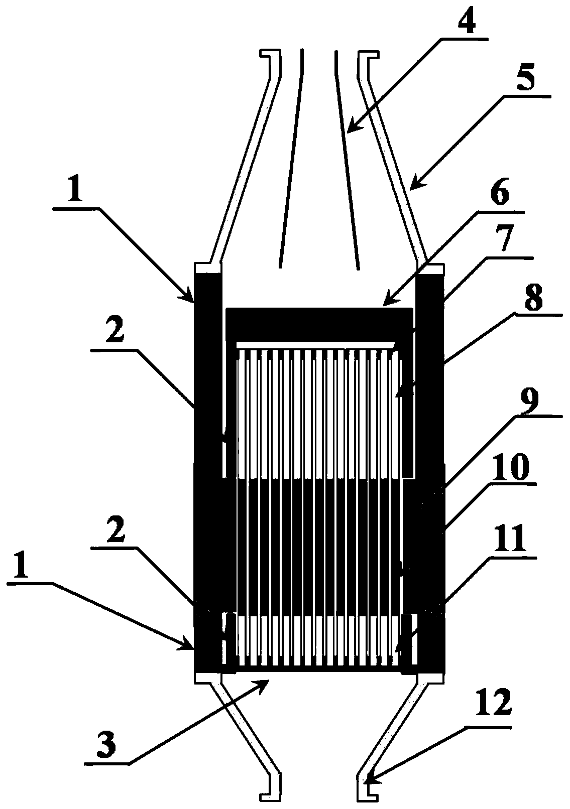
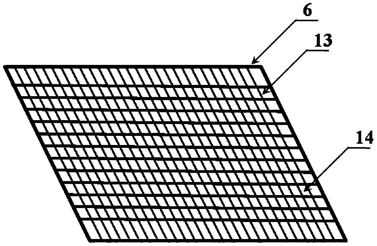
[0034] This embodiment discloses a direct liquid-cooled laser gain device based on a split channel, which includes a direct liquid-cooled array distributed laser gain module and an incoming flow guide cone 5 for splitting and homogenizing cooling liquid; the guide The flow cone 5 is arranged at the inlet of the cooling liquid of the laser gain module. In one embodiment, such as Figure 4 As shown, the incoming flow deflector cone 5 is composed of a conical shell and several cone inner deflectors 4 arranged inside.

[0035] The direct liquid-cooled array distributed laser gain module usually includes a laser window 9 and an arrayed laser gain medium. The arrayed laser gain medium is composed of several thin slices of laser gain medium, and the adjacent slices are separated by microchannel separators 7 Come. Generally speaking, the micro-channel dividing strips 7 are arranged on the four corners of the sheets, so that micro-channels for the cooling liquid to flow are formed be...

Embodiment 2

[0039] Such as figure 1As shown, this embodiment discloses a direct liquid-cooled laser gain device based on a split flow channel, which includes a direct liquid-cooled array distributed laser gain module and an incoming flow guide cone for splitting and homogenizing the cooling liquid 5. The guide cone 5 is arranged at the inlet of the cooling liquid of the laser gain module. The direct liquid-cooled array distributed laser gain module includes a frame structure, a laser window 9 and an arrayed laser gain medium, the laser window 9 is arranged on the frame structure, and the arrayed laser gain medium is arranged on the frame within the body structure.

[0040] The frame structure above includes an outer frame 1 and an inner frame 2 of the device, and the outer frame 1 and the inner frame 2 are designed separately, that is, there is a gap between them. The inner frame 2 is fixedly installed in the outer frame 1, and a laser window 9 is arranged on the outer frame 1 correspon...

Embodiment 3

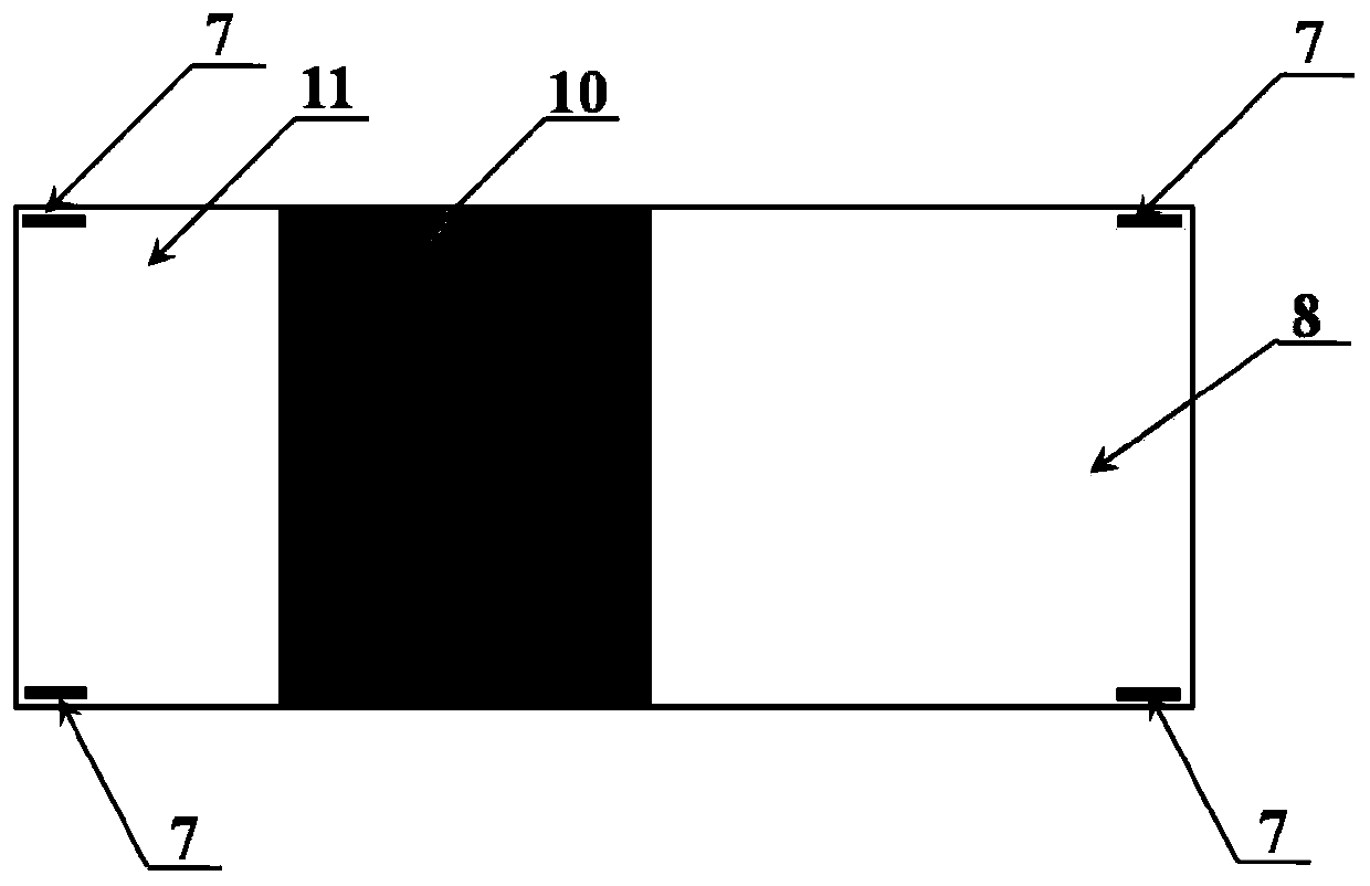
[0042] Such as figure 1 , 2 As shown, this embodiment discloses a structure of an arrayed laser gain medium. It is composed of several thin slices of laser gain medium and micro flow channel separators 7 between adjacent thin slices. Such as figure 2 As shown, the thin slice laser gain medium includes a dissipative segment crystal 8 (i.e. the first segment medium), a gain crystal 10 (i.e. the second segment medium), a recovery segment crystal 11 (i.e. the third segment medium), and between the three segment crystals is One-piece processing, can be connected as a whole by bonding, bonding, etc. Among them, the dissipative segment crystal 8 and the recovery segment crystal 11 are characterized by the fact that the matrix is ​​the same as the gain crystal 10 but the dopant ions are different or have no dopant ions. The thin-sheet laser gain medium can be one or more of crystal, ceramic and glass materials.

[0043] On the four corners of each sheet (or other positions that ...


PUM


Abstract

The invention discloses a direct liquid cooling laser gain device based on a split type flow channel. The device comprises a device outer frame, a device inner frame, a crystal barrier strip, an incoming flow guide cone, a homogenizing grid, a micro-channel separation strip, a dissipation section crystal, a light transmission window, a laser gain crystal, a recovery section crystal and an outflowcone. Cooling liquid flows into the device outer frame after being shunted by an in-cone flow guide plate in the incoming flow guide cone, and enters the device inner frame after being homogenized bythe homogenizing grid. In a micro-channel of the inner frame, turbulent flow is further dissipated by flowing through a dissipation section crystal area firstly, the speed uniformity of liquid reaching the gain crystal in the spanwise direction is guaranteed, and the liquid flows out of the device inner frame after passing through the recovery section crystal. A small amount of liquid flows out through a gap between the inner frame and the outer frame of the device and is used for cooling the laser light transmission window. All liquid flows out of the device after being converged at the outflow cone. The device is compact and small in structure, and the flow velocity of liquid passing through the gain medium can be uniform.

Description

technical field [0001] The invention relates to the technical field of high-energy lasers, in particular to a direct liquid-cooled laser gain device based on split flow channels. Background technique [0002] High-power solid-state lasers are widely used in industry, medical treatment, scientific research, national defense and other fields due to their advantages of large output energy, high peak power, high reliability and long service life. With the increasing demand for lasers in industrial processing, military defense and other fields, higher requirements are put forward for the power, beam quality, volume and weight of lasers. Conventional solid-state laser structures, such as thin-film lasers and slab lasers, have been difficult to meet new requirements in terms of power-to-volume (weight) ratio. Thermal management is a key factor affecting laser power, efficiency, and volumetric weight. With the increase of laser output power, the requirements for thermal management...

Claims


Application Information

Patent Timeline
Patent Type & Authority Applications(China)
IPC IPC(8): H01S3/042H01S3/04
CPCH01S3/042H01S3/0407
Inventor 易家玉阮旭涂波胡浩曹海霞唐淳
Owner INST OF APPLIED ELECTRONICS CHINA ACAD OF ENG PHYSICS
Why Eureka
Try Eureka