
An energy storage system and method

A technology of an energy storage system and a control method, which is applied in the field of energy storage systems to achieve the effects of improving balance accuracy, improving adaptability and flexibility, and high current sharing accuracy

Active Publication Date: 2021-09-17
SHANDONG LUNENG SOFTWARE TECH
View PDF7 Cites 0 Cited by
  • Summary
  • Abstract
  • Description
  • Claims
  • Application Information

AI Technical Summary

Problems solved by technology

[0009] In order to solve the above problems, the present invention proposes an energy storage system and method. For the control of parallel energy storage converters, after the parallel / grid-connected control cabinet performs the outer loop PI calculation, the current inner loop reference is distributed to each parallel PCS, each parallel PCS performs the current inner loop operation separately, which can effectively eliminate the unbalanced problem of each energy storage converter’s sampling and outer loop calculation errors; the energy storage system communicates with the energy management system EMS, and can command or determine the operating mode of the system according to the operating state of the system, and generate the corresponding energy storage converter control reference

Method used


Image

  • An energy storage system and method
  • An energy storage system and method
  • An energy storage system and method

Examples


Embodiment 1

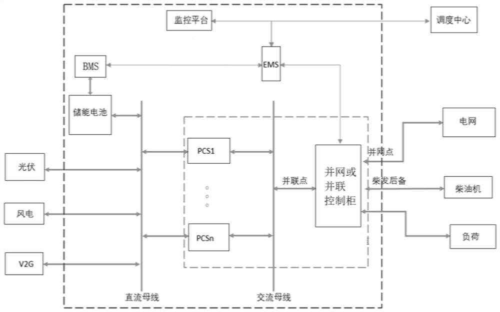
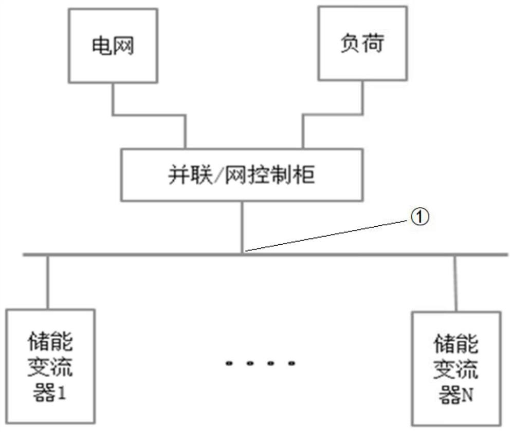
[0057] In one or more embodiments, an energy storage system is disclosed, such as figure 1 and figure 2 As shown, including: 1 set of parallel / grid-connected control cabinet and multiple sets of energy storage converters (PCS), the number of energy storage converters is N, and N is greater than 1. The parallel / grid-connected control cabinet has N+2 ports, N ports are connected to the energy storage converter in parallel, 1 grid-connected port, and 1 off-grid port (load port); There is a backup port for diesel generator; if there is a backup port for diesel generator, a bypass switch should be configured in the grid-connected / connected control cabinet.

[0058] The bypass switch is set between the diesel generator and the load. When the power grid fails, the load can no longer obtain energy from the grid, and the system cannot meet the demand, the bypass switch is closed, the diesel generator is put into operation, and the off-grid operation energy is maintained. balance.

...

Embodiment 2

[0102] In one or more embodiments, a control method of an energy storage system is disclosed, refer to Image 6 , when the grid-connected or parallel control cabinet works in the grid-connected mode, the specific process includes the following:

[0103] 1) Collect the three-phase voltage and three-phase current of the grid connection point;

[0104] 2) Phase-lock the three-phase voltage of the grid connection point to obtain the operating frequency of the grid;

[0105] 3) The dq transformation module performs αβ / dq transformation on the collected three-phase voltage and three-phase current to obtain the actual total feedback voltage and feedback current in the two-phase synchronous rotating coordinate system;

[0106] 4) The instantaneous power conversion module determines the instantaneous active power and instantaneous reactive power of the grid-connected point according to the following formula according to the actual total feedback voltage and feedback current obtained i...

Embodiment 3

[0116] In one or more embodiments, a control method of an energy storage system is disclosed, refer to Figure 7 , when the grid-connected or parallel control cabinet works in the parallel mode, the specific process includes the following:

[0117] 1) Collect the three-phase voltage and three-phase current of the parallel point;

[0118] 2) Phase-lock the three-phase voltage of the grid-connected point to obtain the frequency feedback f of the grid-connected point;

[0119] 3) The amplitude calculation module obtains the voltage and current feedback amplitudes u and i of the grid connection point according to the collected three-phase voltage and three-phase current;

[0120] 4) Take the parallel point feedback frequency f, the feedback voltage u and the reference frequency f ref =50Hz reference voltage amplitude u ref =220 or 380V comparison, get the frequency error δf and voltage amplitude error δu, respectively carry out the proportional integral operation to obtain the ...


PUM


Abstract

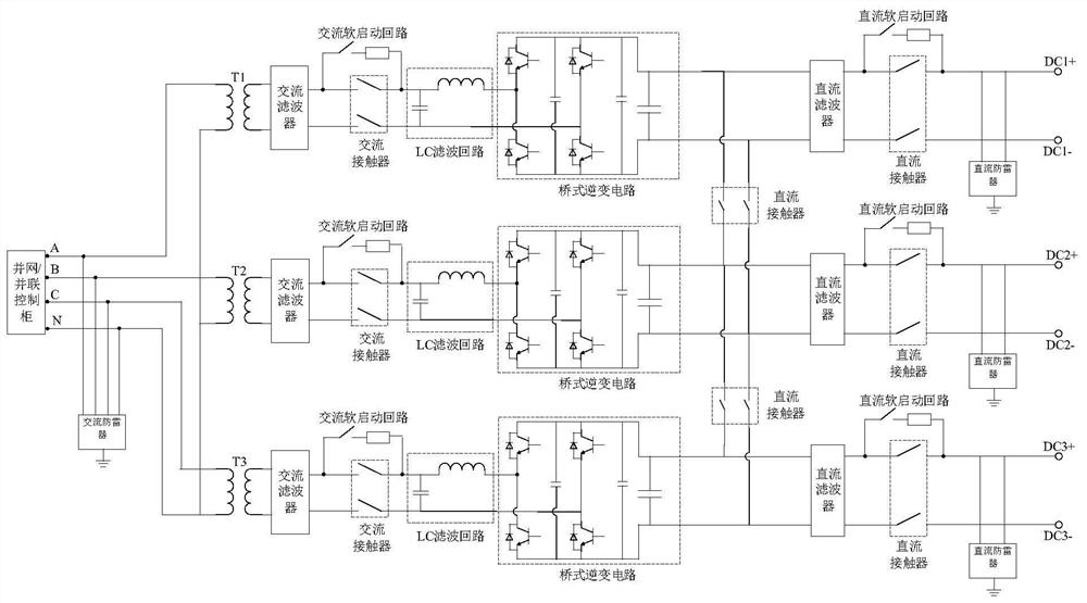
The invention discloses an energy storage system and a control method, comprising: a plurality of energy storage converters connected in parallel between a DC bus and an AC bus; the DC side of the energy storage converter is connected to a battery pack through the DC bus, and the battery pack Connected with the battery management system, the AC side of the energy storage converter is connected in parallel through the AC bus, and then connected to the grid-connected or parallel control cabinet; the grid-connected or parallel control cabinet is respectively equipped with ports for connecting to the grid and loads. The grid-connected or parallel control cabinet obtains the current component reference value of the current inner loop through the outer loop control, and sends the obtained current component reference value to each energy storage converter in parallel; each energy storage converter according to the received The reference values ​​of the current components are respectively subjected to the current inner loop operation to obtain the driving signal for driving the switching tube of the energy storage converter to be turned on and off. The beneficial effect of the invention is that the detection and control of the outer loop are completed by the parallel / grid-connected control cabinet, which eliminates the unbalance of separate sampling and calculation errors of the outer loop.

Description

technical field [0001] The present invention relates to the technical field of energy storage converters, and in particular, to an energy storage system and method. Background technique [0002] The statements in this section merely provide background information related to the present invention and do not necessarily constitute prior art. [0003] At present, the new energy industry is developing rapidly. In order to stabilize the fluctuation of distributed new energy, energy storage systems are often equipped. In the energy storage system, the energy storage converter (PCS) makes the output of the distributed new energy microgrid system controllable according to the preset management strategy, effectively suppresses the rapid fluctuation of grid-connected power, and is grid-friendly. [0004] As the capacity of the new energy microgrid continues to increase, it is necessary to configure a larger-capacity energy storage converter. Considering the power level of the energy ...

Claims


Application Information

Patent Timeline
Patent Type & Authority Patents(China)
IPC IPC(8): H02J3/32H02J3/46
CPCH02J3/32H02J3/46
Inventor 黄德旭王培仑孙永亮丁玉华孙久军李志高任士康刘雷胡勇刘爱忠李豹杨宁段连君
Owner SHANDONG LUNENG SOFTWARE TECH
Learn More