High-efficiency module combined type photovoltaic inverter

A photovoltaic inverter and combined technology, applied in the photovoltaic field, can solve the problems of consuming power generation, reducing grid connection efficiency, losing power generation benefits, etc., to achieve the effects of simplifying control methods, high power generation efficiency, and improving reliability

Pending Publication Date: 2020-06-19
LIUAN POWER SUPPLY COMPANY STATE GRID ANHUI ELECTRIC POWER +1
View PDF2 Cites 2 Cited by
  • Summary
  • Abstract
  • Description
  • Claims
  • Application Information

AI Technical Summary

Problems solved by technology

[0003] The patent with the notification number CN202406054U discloses a photovoltaic inverter main topology circuit, which applies the traditional three-phase full-bridge inverter to the photovoltaic grid-connected system. Although the circuit has obvious advantages in structure, it has In order to cooperate with this structure, a large number of photovoltaic modules need to be boosted in series, and the higher DC bus voltage is gathered as the input pole of the inverter. This will cause the photovoltaic modules that generate electricity to become loads due to inconsistent output characteristics of the photovoltaic modules, consuming power generation, greatly reducing the efficiency of grid connection
[0004] The patent with the notification number CN204334377U discloses a micro photovoltaic inverter based on a flyback transformer, which can improve the distortion of the grid-connected current, but the topology of the micro inverter is complex, and each photovoltaic module output needs A set of independent booster circuit, grid-connected circuit and control circuit has high cost and is not conducive to engineering application
[0005] Series boosting is the simplest and cheapest way to obtain high voltage technology, but the simple series connection of photovoltaic modules loses the power generation efficiency, so it is urgent to provide a new type of photovoltaic inverter to solve the above problems

Method used


Image

  • High-efficiency module combined type photovoltaic inverter
  • High-efficiency module combined type photovoltaic inverter
  • High-efficiency module combined type photovoltaic inverter

Examples


Embodiment Construction

[0021] The preferred embodiments of the present invention will be described in detail below in conjunction with the accompanying drawings, so that the advantages and features of the present invention can be more easily understood by those skilled in the art, so as to define the protection scope of the present invention more clearly.

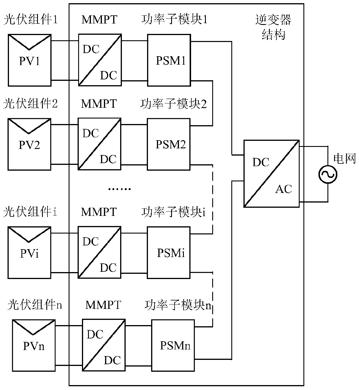
[0022] see figure 1 , the embodiment of the present invention includes:

[0023] A high-efficiency module-combined photovoltaic inverter mainly includes n DC / DC conversion circuits, n power sub-modules, and 1 DC / AC conversion circuit. The input terminal of each DC / DC conversion circuit is connected to a photovoltaic module, and the output terminal is connected to a power sub-module (PSM). The n power sub-modules are connected in series and then connected to the input pole of the DC / AC conversion circuit. The positive and negative poles of the DC / AC conversion circuit are connected to form a complete circuit, and the output of the DC / AC conversio...


PUM


Abstract

The invention discloses a high-efficiency module combined type photovoltaic inverter which comprises three parts, namely n DC / DC conversion circuits, n power sub-modules and a DC / AC conversion circuit. The inputs of the n DC / DC conversion circuits are connected with n photovoltaic modules, and the outputs of the n DC / DC conversion circuits are connected with n PSMs; the n PSMs are connected in series and then are connected with the input electrode of the DC / AC conversion circuit; and the output of the DC / AC conversion circuit is an alternating-current power grid or a load. According to the invention, the modules are combined and superposed to form multiple levels to realize high-voltage output; each photovoltaic module has independent MPPT control, so that the defect that the output powerof string-type and array-type inverters is reduced due to characteristic differentiation and local shadows of the photovoltaic modules is overcome, and the power generation efficiency of the system ishigher; the cost is low; only one DC / AC circuit is used at the output end, and power flow can be inverted in a centralized mode through power frequency overturning conversion; and multiple assembliesshare the inverter circuit, and thus the cost of the grid-connected link is saved.

Description

technical field [0001] The invention relates to the photovoltaic field, in particular to a high-efficiency module-combined photovoltaic inverter. Background technique [0002] As the cleanest energy source, solar energy has been widely used in recent years. The most common way of photoelectric conversion is photovoltaic power generation, and the open circuit voltage of a single photovoltaic module is a low voltage of about 30V-50V. Many topological structures have been proposed to achieve low voltage and network requirements. [0003] The patent with the notification number CN202406054U discloses a photovoltaic inverter main topology circuit, which applies the traditional three-phase full-bridge inverter to the photovoltaic grid-connected system. Although the circuit has obvious advantages in structure, it has In order to cooperate with this structure, a large number of photovoltaic modules need to be boosted in series, and the higher DC bus voltage is gathered as the input...

Claims


Application Information

Patent Timeline
Patent Type & Authority Applications(China)
IPC IPC(8): H02J3/38H02M7/497
CPCH02M7/497Y02E10/56
Inventor 柏同杨费传学洪瑞王杰吴斌
Owner LIUAN POWER SUPPLY COMPANY STATE GRID ANHUI ELECTRIC POWER
Why Eureka
Try Eureka