
Optical module

A technology of optical modules and lasers, which is applied in the field of optical communications, can solve problems such as ineffective power loss, hinder heat dissipation of dies, and reduce efficiency, and achieve the effects of avoiding heat loss, improving heating efficiency, and widening the wavelength range

Pending Publication Date: 2020-06-23
易锐光电科技(安徽)有限公司 +1
View PDF0 Cites 0 Cited by
  • Summary
  • Abstract
  • Description
  • Claims
  • Application Information

AI Technical Summary

Problems solved by technology

The traditional technical solution is to use a thermoelectric cooler TEC (Thermal Electric Cooler) to control the working environment temperature of the laser, but since the TEC needs a dedicated chip to control it when it works, and the TEC is in the heating and cooling working state, as the temperature control range increases increase, the efficiency will decrease, resulting in a large amount of ineffective power loss
With the limitation of module power consumption, it often cannot meet the actual module usage requirements
The 5G optical fiber transmission network has strict requirements on the cost and power consumption of optical modules. At present, in order to be able to work in an industrial temperature environment (-40°C-85°C), a heating sheet is mounted outside the laser, or a heating resistance wire is wound. , the heat is transferred to the internal laser through heat conduction, but this method has low heat conduction efficiency and high power consumption, and also increases the device volume
In addition, the laser and the heater are placed on the thermally isolated substrate. Although this method has a good heating effect at low temperature, the thermally isolated substrate will hinder the heat dissipation of the die, reducing the ability of the component to adapt to the high temperature environment.
Another method is to set the heater on the carrier close to the laser chip. However, the carrier connected to the laser chip needs to be heated together. The volume of the carrier is much larger than the volume of the laser. Most of the heat in the heating state is used for carrier heating. , causing inefficiency

Method used


Image

  • Optical module
  • Optical module
  • Optical module

Examples


Embodiment Construction

[0027] The technical solutions of the present invention will be clearly and completely described below in conjunction with the accompanying drawings. Apparently, the described embodiments are some of the embodiments of the present invention, but not all of them. Based on the embodiments of the present invention, all other embodiments obtained by persons of ordinary skill in the art without making creative efforts belong to the protection scope of the present invention.

[0028] In the description of the present invention, it should be noted that the terms "center", "upper", "lower", "left", "right", "vertical", "horizontal", "inner", "outer" etc. The indicated orientation or positional relationship is based on the orientation or positional relationship shown in the drawings, and is only for the convenience of describing the present invention and simplifying the description, rather than indicating or implying that the referred mechanism or element must have a specific orientatio...


PUM


Abstract

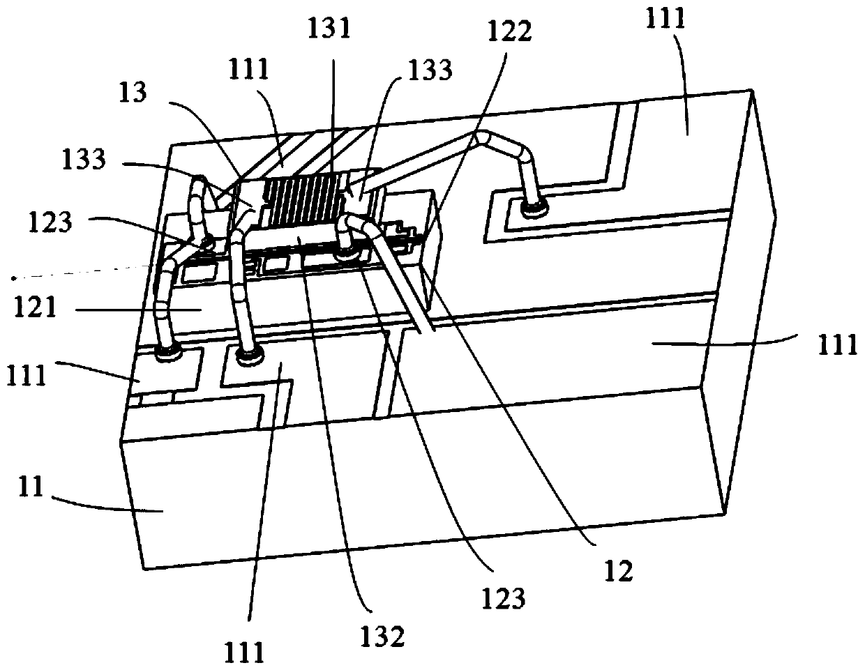
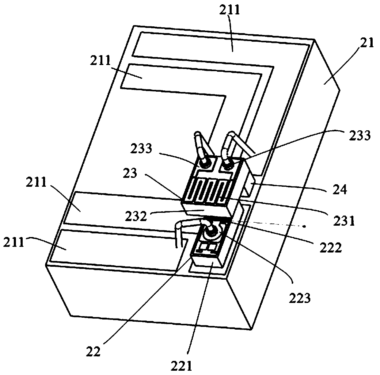
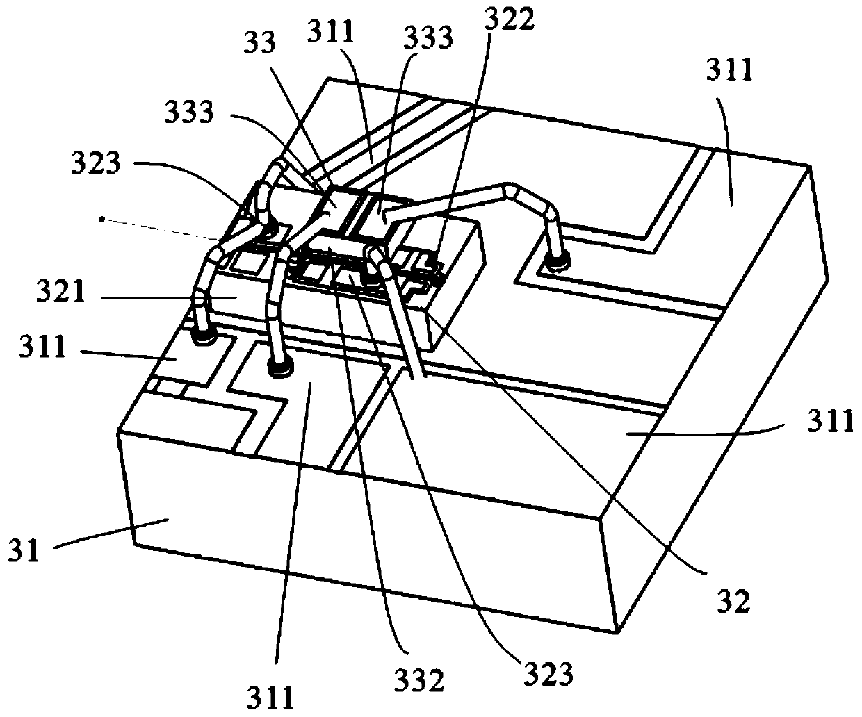
A laser chip in an optical module comprises a substrate and a waveguide integrated on the upper surface of the substrate, a heating unit for performing temperature compensation on the waveguide is also arranged on the upper surface of the substrate; the heating unit is close to the waveguide. The heating unit for performing temperature compensation on the waveguide is arranged at a position, closeto the waveguide, of the upper surface of the substrate of the laser chip, so that direct heat transfer between the heating unit and the waveguide is realized, thereby avoiding loss of heat, greatlyimproving heating efficiency, reducing power consumption, therefore, tuning of the central wavelength of the laser chip in an industrial-grade temperature range is easily realized, the optical modulemeeting the 5G forward transmission MWDM wavelength range is obtained; the wavelength range of the laser chip is broadened, the power consumption level of the optical module is reduced, the yield of the laser chip is improved, and the 5G forward transmission application scene can be realized, so that expensive TEC is not used for temperature tuning any more, and the material cost of the 5G forwardtransmission optical module is saved.

Description

technical field [0001] The invention relates to an optical module and belongs to the technical field of optical communication. Background technique [0002] For optical fiber communication systems, in order to make full use of the advantages of optical fiber in transmission capacity, it is necessary to build a wavelength division multiplexing system. According to the traditional division method, the optical fiber transmission bandwidth can be divided into sparse wavelength division multiplexing CWDM (CoarseWavelength Division Multiplexing) according to the grid. ) interval, dense wavelength division multiplexing interval, and Lan-WDM multiplexing interval. With the construction of the 5G system, a new division method of the WDM network is proposed, which is called the Open-WDM / MWDM solution. The working wavelength of the laser chip has a certain drift with the temperature change, and the drift coefficient is about 0.1nm / ℃. Under the ambient temperature of the working temper...

Claims


Application Information

Patent Timeline
Patent Type & Authority Applications(China)
IPC IPC(8): G02B6/42
CPCG02B6/4266G02B6/428
Inventor 徐俊郑睿陈亦凡
Owner 易锐光电科技(安徽)有限公司
Learn More