
Manufacturing method of semiconductor device

A manufacturing method and semiconductor technology, applied in semiconductor/solid-state device manufacturing, semiconductor devices, electric solid-state devices, etc., can solve problems such as low chip yield, white pixel defects, and image noise, and achieve less dislocations and improve signal quality. The effect of noise ratio and good picture effect

Active Publication Date: 2020-03-20
SHANGHAI INTEGRATED CIRCUIT RES & DEV CENT
View PDF4 Cites 0 Cited by
  • Summary
  • Abstract
  • Description
  • Claims
  • Application Information

AI Technical Summary

Problems solved by technology

Under such process conditions, white pixel defects usually occur, and the dark current is too large, resulting in more noise in the image, resulting in low chip yield
Especially when collecting images under low-light conditions, a relatively high gain is usually applied due to insufficient sensitivity, so that the noise is also amplified synchronously, making the picture effect worse

Method used


Image

  • Manufacturing method of semiconductor device
  • Manufacturing method of semiconductor device
  • Manufacturing method of semiconductor device

Examples


Embodiment 1

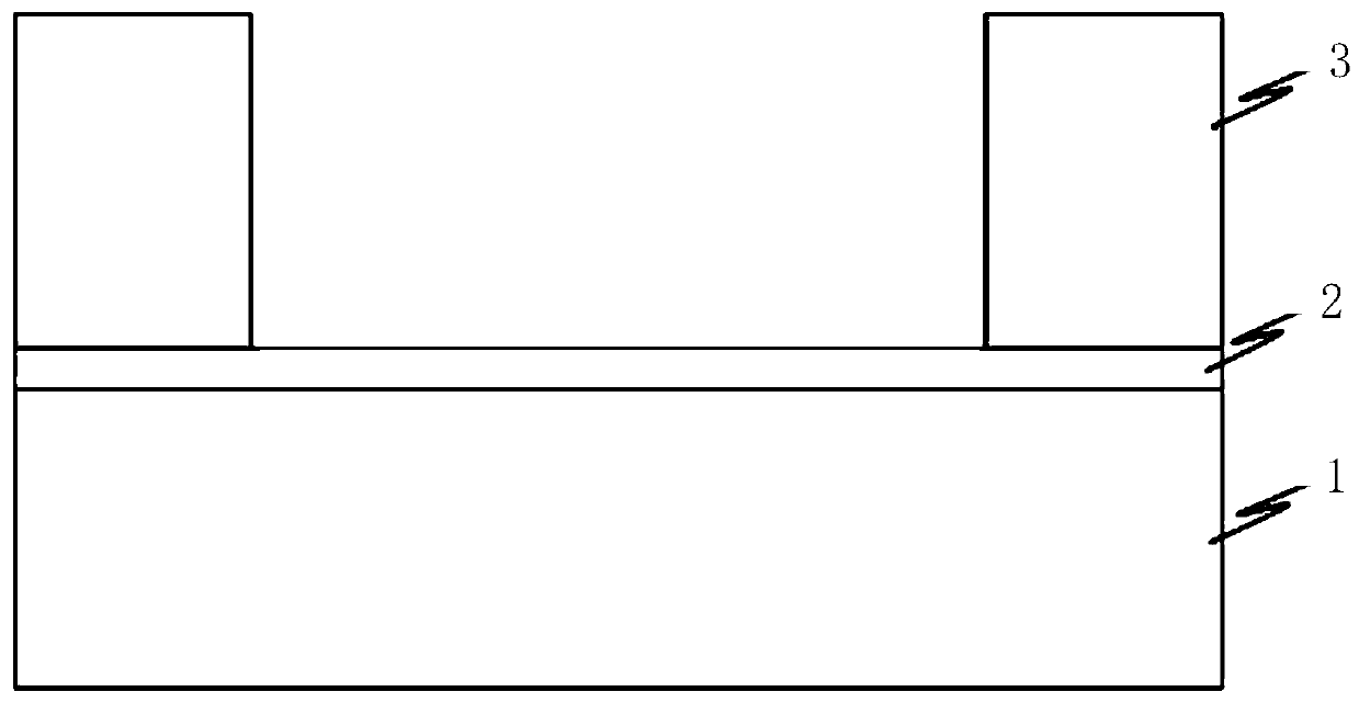
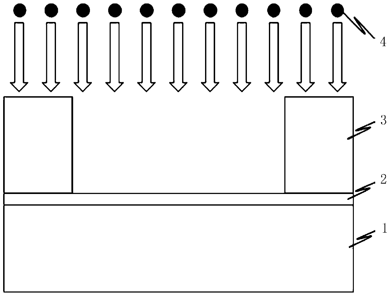
[0030] In the following specific embodiments of the present invention, please refer to Figure 1a ~ Figure 1f , Figure 1a ~ Figure 1f It is a schematic process flow diagram of Embodiment 1 of the present invention. Such as Figure 1a ~ Figure 1f Shown, a kind of manufacturing method of semiconductor device of the present invention comprises the following steps:

[0031] 1) After conventional RCA cleaning of the semiconductor substrate, a silicon dioxide film is formed on the surface of the substrate.

[0032] Such as Figure 1a As shown, in this embodiment, an N-type semiconductor epitaxial wafer with a substrate resistivity of 80-100 Ω·cm and a crystal orientation of (100), such as an epitaxial silicon wafer, can be used as the semiconductor substrate 1 . The present invention is not limited thereto. Firstly, the semiconductor substrate 1 is cleaned by conventional RCA, and the cleaning solution can be SC1, HF, and SC2. Then, a layer of silicon dioxide 2 can be formed ...

Embodiment 2

[0051] In the following specific embodiments of the present invention, please refer to Figure 2a ~ Figure 2f , Figure 2a ~ Figure 2f It is a schematic process flow diagram of Embodiment 2 of the present invention. Such as Figure 2a ~ Figure 2f Shown, a kind of manufacturing method of semiconductor device of the present invention comprises the following steps:

[0052] 1) After conventional RCA cleaning of the semiconductor substrate, a silicon dioxide film is formed on the surface of the substrate.

[0053] Such as Figure 2a As shown, in this embodiment, an N-type semiconductor epitaxial wafer with a substrate resistivity of 80-100 Ω·cm and a crystal orientation of (100), such as an epitaxial silicon wafer, can also be used as the semiconductor substrate 1 . The present invention is not limited thereto. Firstly, the semiconductor substrate 1 is cleaned by conventional RCA, and the cleaning solution can be SC1, HF, and SC2. Then, a layer of silicon dioxide 2 can be fo...


PUM

PropertyMeasurementUnit
wavelengthaaaaaaaaaa
electrical resistivityaaaaaaaaaa
thicknessaaaaaaaaaa

Abstract

The invention discloses a manufacturing method of a semiconductor device. In annealing and re-crystallization technologies, the wavelength range of electromagnetic waves is expanded from a visible light waveband to an infrared light waveband. when the atomic radius of injected impurities is greater than that of semiconductor substrate elements, the annealing process of the infrared waveband, on the basis of a traditional annealing technology, can reach a deeper area under the surface of a silicon chip, and thus, the recrystallization recovery capability of the substrate is improved, crystal lattice displacement of a deep doped area can be reduced, diffusion of metal impurities to the semiconductor substrate is inhibited, and defects of white pixels can be eliminated effectively.

Description

technical field [0001] The present invention relates to semiconductor production processes, and more particularly, to implantation and annealing processes in the manufacture of image sensors. Background technique [0002] The present invention is related to ion implantation and annealing recrystallization processes in the production of image sensors. [0003] Traditionally, in the integrated circuit manufacturing process of an image sensor, ion implantation and annealing heat treatment processes are usually used to form a specific impurity distribution in the image sensor device, which requires a highly doped junction with electrical activity. [0004] Generally, various ion sources are used for ion implantation, and a subsequent annealing and activation process is performed using a conventional method to form an impurity layer. In the traditional annealing and recrystallization process, electromagnetic waves in the visible light band are generally used for irradiation. Un...

Claims


Application Information

Patent Timeline
Patent Type & Authority Patents(China)
IPC IPC(8): H01L27/146H01L21/265H01L21/268
CPCH01L21/26506H01L21/268H01L27/14683H01L27/14698
Inventor 龟井诚司
Owner SHANGHAI INTEGRATED CIRCUIT RES & DEV CENT
Learn More