A membrane electrode comprising an ordered catalytic layer and its preparation method and application

A technology for ordering catalytic layers and membrane electrodes, applied in battery electrodes, circuits, fuel cells, etc., can solve problems such as poor performance, limited electronic resistance, etc., to reduce the amount of Pt used, reduce mass transfer polarization, and improve Effect of Catalyst Utilization

Active Publication Date: 2021-06-08
DALIAN INST OF CHEM PHYSICS CHINESE ACAD OF SCI
View PDF6 Cites 0 Cited by
  • Summary
  • Abstract
  • Description
  • Claims
  • Application Information

AI Technical Summary

Problems solved by technology

[0003] According to the idea of ​​NSTF, the article Chemsuschem, 2013, 6, 659-666 developed an ordered electrode structure based on a non-conductive TiO2 nanotube array. The electrode has good stability, but due to the limited electronic resistance, the performance is not good.

Method used


Image

  • A membrane electrode comprising an ordered catalytic layer and its preparation method and application
  • A membrane electrode comprising an ordered catalytic layer and its preparation method and application
  • A membrane electrode comprising an ordered catalytic layer and its preparation method and application

Examples


Embodiment 1

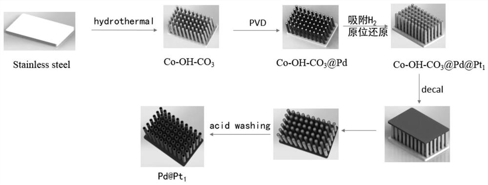
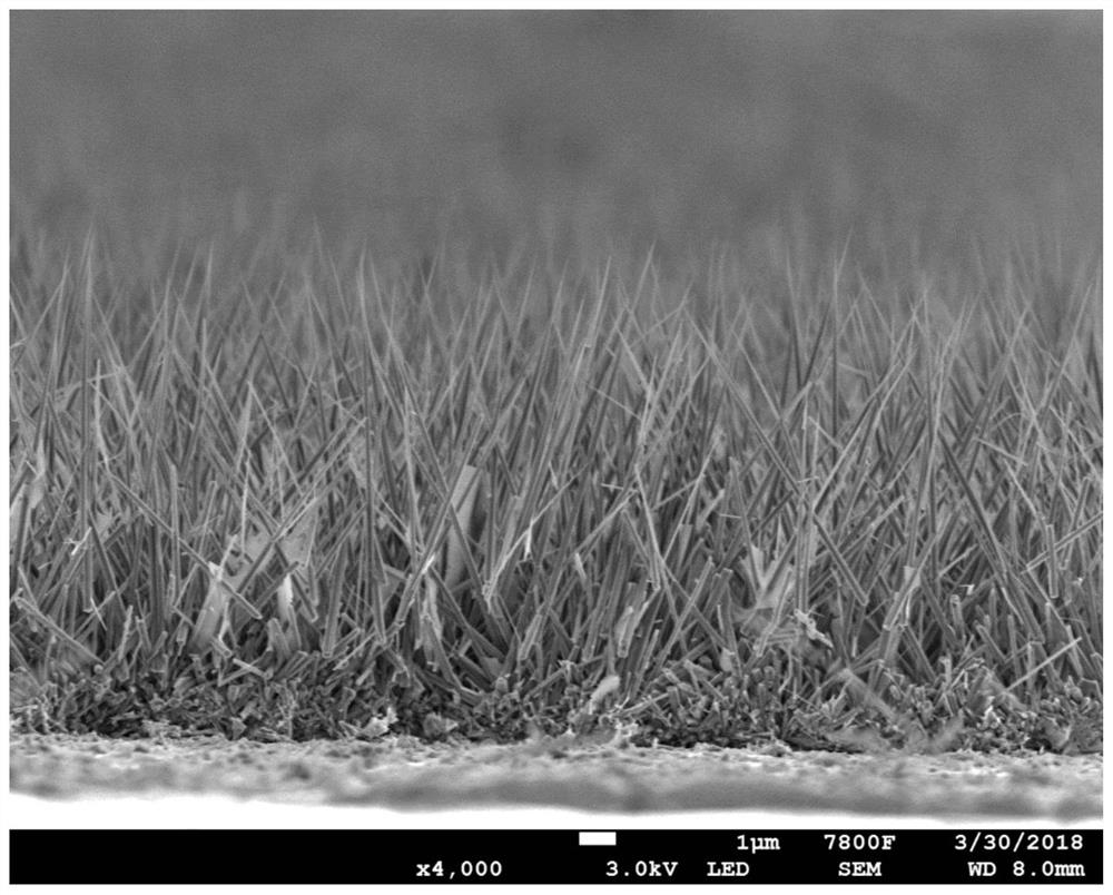
[0031] Step 1: Growth of Co-OH-CO on the surface of stainless steel sheet 3 nanorod arrays. Reaction temperature 120°C, reaction solution: reaction solution: 20mM Co(NO 3 ) 2 ·6H 2 O, 20mM NH 4 F, 40mM CO(NH 2 ) 2 , the array has a length of 5 μm and a diameter of 200-300 nm.

[0032] Step 2: PVD on Co-OH-CO 3 A layer of adsorbable H is deposited on the surface 2 metal Pd. The mode of physical vapor deposition adopts the mode of magnetron sputtering, and the ultimate vacuum pressure is 3.8×10 -3 Pa, working pressure 0.8Pa, power 120W, Ar gas flow 400sccm, time 15min.

[0033] Step 3: H on the Pd surface 2 Preparation of Pt thin-layer catalysts by adsorption and reduction. will grow Co-OH-CO 3 The substrate of the @Pd nanorod array is placed obliquely in a beaker filled with deionized water, and the water containing H 2 Atmosphere, the concentration of the atmosphere is 100vol.%, the gas flow rate is 40sccm, and the ventilation time is 15min. The reduction proces...

Embodiment 2

[0038] Step 1: Growth of Co-OH-CO on the surface of stainless steel sheet 3 nanorod arrays. Reaction temperature 120°C, reaction solution: reaction solution: 20mM Co(NO 3 ) 2 ·6H 2 O, 20mM NH 4 F,40mMCO(NH 2 ) 2 , the array has a length of 5 μm and a diameter of 200-300 nm.

[0039] Step 2: PVD on Co-OH-CO 3 A layer of adsorbable H is deposited on the surface 2 metal Pd. The mode of physical vapor deposition adopts the mode of magnetron sputtering, and the ultimate vacuum pressure is 3.8×10 -3 Pa, working pressure 0.8Pa, power 120W, Ar gas flow 400sccm, time 15min.

[0040] Step 3: CO adsorption and reduction on Pd surface to prepare Pt thin-layer catalyst. will grow Co-OH-CO 3 The substrate of the @Pd nanorod array was placed obliquely in a beaker filled with deionized water, and an atmosphere containing CO was introduced into the water with an atmosphere concentration of 100vol.%, a gas flow rate of 40sccm, and an aeration time of 15min. The reduction process is...


PUM

PropertyMeasurementUnit
thicknessaaaaaaaaaa
lengthaaaaaaaaaa
thicknessaaaaaaaaaa

Abstract

The invention describes an ordered catalytic layer of a membrane electrode, including the construction of an ordered structure, the formation of a metal / alloy that can absorb hydrogen / CO, and the in-situ reduction preparation of a thin-layer catalyst. Some metals or alloys have adsorbed H 2 and the role of CO, the adsorbed H 2 and CO have reducing properties for the preparation of thin-layer catalysts, and the loading of the catalyst is determined by the adsorbed H 2 / CO volume control. The membrane electrode structure prepared by the invention has the advantages of low catalyst loading, high catalyst utilization rate, excellent mass transfer, high stability and the like, while avoiding the use of ion polymers in the catalytic layer as proton conductors.

Description

technical field [0001] The invention relates to a method for preparing a thin-layer catalyst in an ordered electrode, belonging to the field of fuel cells. Background technique [0002] Fuel cell is an energy conversion device with the advantages of cleanliness, high efficiency, and high specific energy. It has been used in aerospace, underwater equipment, military industry, distributed power stations, and new energy vehicles. However, the cost has always been a major reason for limiting the large-scale application of fuel cells. A large amount of noble metal Pt is used as a catalyst in fuel cells, but its price is high. Therefore, it is extremely necessary to reduce the amount of Pt catalyst used and improve the utilization rate. In traditional membrane electrodes, catalyst particles and ionic polymers used as proton conductors are distributed disorderly, resulting in large mass transfer polarization, low catalyst utilization, and large catalyst loading capacity. In respon...

Claims


Application Information

Patent Timeline
Patent Type & Authority Patents(China)
IPC IPC(8): H01M8/1004H01M8/0247H01M8/0226H01M4/88H01M4/86
CPCH01M4/8652H01M4/8871H01M8/0226H01M8/0247H01M8/1004Y02E60/50
Inventor 俞红梅姚德伟高学强覃博文孙昕野姜广范芷萱秦晓平邵志刚
Owner DALIAN INST OF CHEM PHYSICS CHINESE ACAD OF SCI
Why Eureka
Try Eureka