Laser stirring welding device with tactile tracking

A welding device and laser technology, applied in laser welding equipment, welding equipment, metal processing equipment and other directions, can solve the problems of complex structure and cost of tactile sensor, less combination of welding seam tracking technology, limited use efficiency, etc., to achieve simple structure, improved The effect of welding seam quality and improving welding efficiency

Active Publication Date: 2020-06-26
武汉新耐视智能科技有限责任公司
View PDF11 Cites 6 Cited by
  • Summary
  • Abstract
  • Description
  • Claims
  • Application Information

AI Technical Summary

Problems solved by technology

[0003] In terms of seam tracking, existing technologies such as common visual sensors need to overcome the strong reflection of light during the welding process, the image is easily mixed with noise, and complex follow-up processing is required to ensure tracking accuracy. Compared with tactile sensors, the structure is more complex, more expensive
In addition, the current laser stir welding (wobble) device is mainly used to complete the welding task of specific materials such as aluminum alloys, and its combination with seam tracking technology is relatively seldom, which limits its use efficiency to a certain extent

Method used


Image

  • Laser stirring welding device with tactile tracking
  • Laser stirring welding device with tactile tracking
  • Laser stirring welding device with tactile tracking

Examples


Embodiment Construction

[0033] In order to make the object, technical solution and advantages of the present invention clearer, the present invention will be further described in detail below in conjunction with the accompanying drawings and embodiments. It should be understood that the specific embodiments described here are only used to explain the present invention, not to limit the present invention. In addition, the technical features involved in the various embodiments of the present invention described below can be combined with each other as long as they do not constitute a conflict with each other.

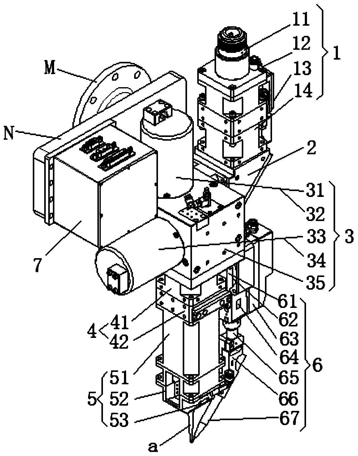
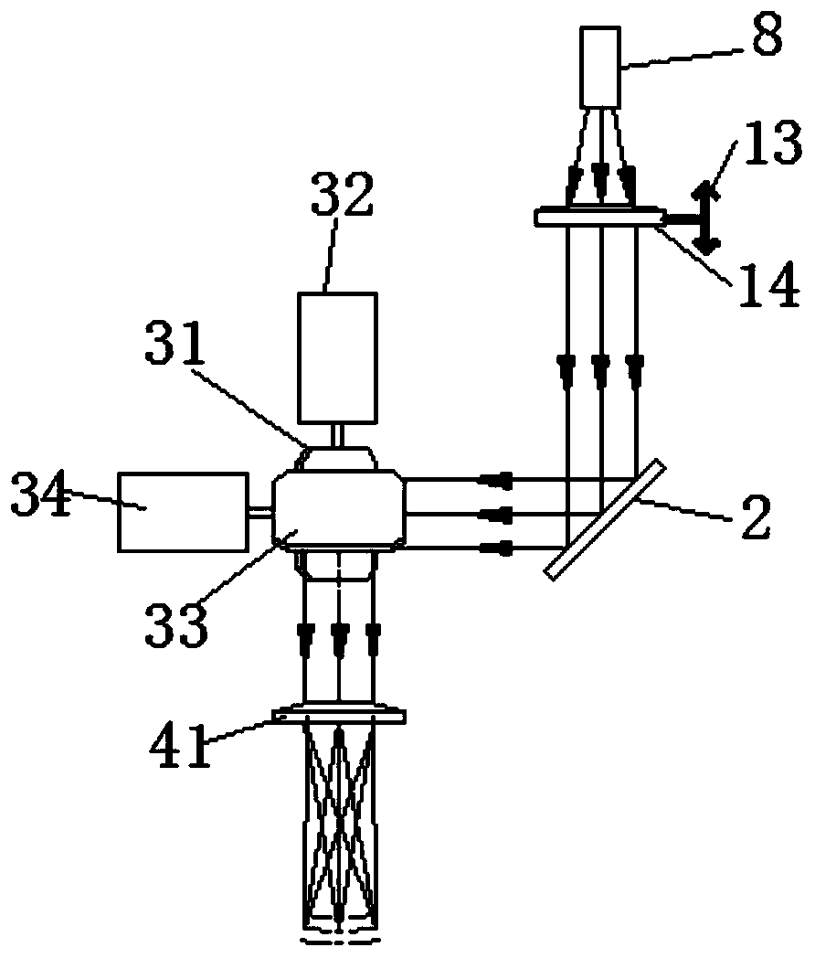
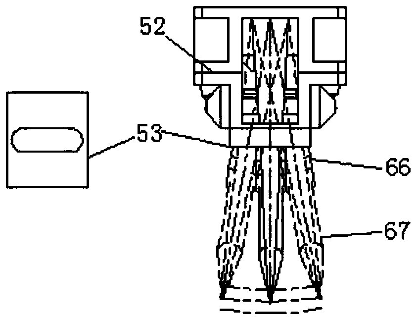
[0034] Such as Figure 1 to Figure 4 As shown, a tactile tracking laser stir welding device includes a housing, a collimation component 1, a mirror group 2, a numerically controlled mirror component 3, a focusing component 4 and a tactile tracking component 6, wherein:

[0035] The housing includes a collimating mirror main body seat, a mirror fixing seat, a numerically controlled mirror fixing...


PUM


Abstract

The invention discloses a laser stirring welding device with tactile tracking. The laser stirring welding device with tactile tracking comprises a shell, a collimating assembly, a mirror group, a numerical control mirror assembly, a focusing assembly and a tactile tracking assembly. The collimating assembly comprises an optical fiber interface and a collimating mirror; the mirror group comprises afixed mirror installed in the shell; the numerical control mirror assembly comprises a numerical control mirror and a numerical control mirror driving mechanism. A focusing mirror group comprises a focusing mirror installed in the shell; the tactile tracking assembly comprises a swinging seat, a motor, a guide pin and an encoder, and the guide pin is installed on the swinging seat; and the encoder is connected with a motor shaft of the motor. A control box assembly drives the numerical control mirror to rotate through the driving mechanism, so that spot formed by the concentrated laser on a workpiece is moved to the specified position, and the workpiece is welded by different laser stirring trajectory patterns according the requirements. Irregular welding seams can be compensated and tracked in real time, stability and reliability are achieved, the efficiency is relatively high, energy can be evenly distributed in wide welding seams, and relatively large depth of fusion is achieved.

Description

technical field [0001] The invention belongs to the field of welding technology, and more specifically relates to a laser stirring welding device. Background technique [0002] Weld seam tracking is of great significance in welding automation. It plays a positive role in improving the flexibility of welding equipment and ensuring welding quality. Especially when welding with complex weld shapes, simple machine trajectory teaching cannot guarantee welding quality. With the increasing demand for welding of large and thick steel plates such as ships, pressure vessels, and nuclear power plants, comprehensive indicators such as weld shape, width, and penetration depth have also been further improved, which puts forward higher requirements for existing welding equipment. [0003] In terms of seam tracking, existing technologies such as common visual sensors need to overcome the strong reflection of light during the welding process, the image is easily mixed with noise, and complex...

Claims


Application Information

Patent Timeline
Patent Type & Authority Applications(China)
IPC IPC(8): B23K26/044B23K26/24B23K26/70
CPCB23K26/24B23K26/044B23K26/702
Inventor 李斌蒋平程思陈文效陈科滑双东
Owner 武汉新耐视智能科技有限责任公司
Why Eureka
Try Eureka