
Grease waste liquid treatment device

A waste liquid treatment and grease technology, which is applied in the direction of grease/oily substance/suspton removal device, water treatment under temperature conditions, biological water/sewage treatment, etc., can solve the problem of affecting the normal metabolic process of activated sludge and biofilm, and affecting aquatic The living environment of organisms and fish, and the impact on the water passing capacity of urban drainage pipe networks, etc., to speed up the oil-water separation rate, improve the oil-water separation effect, and facilitate the separation effect

Inactive Publication Date: 2020-06-26
SOUTHWEST JIAOTONG UNIV
View PDF6 Cites 1 Cited by
  • Summary
  • Abstract
  • Description
  • Claims
  • Application Information

AI Technical Summary

Problems solved by technology

If the untreated kitchen grease waste liquid is directly discharged to natural water bodies, it will not only reduce the reoxygenation rate of the water body, but also consume dissolved oxygen in the water, deteriorate the water quality, and seriously affect the living environment of aquatic organisms and fish; if directly discharged As far as urban sewage treatment plants are concerned, due to the refractory nature of grease, an oil film will be formed on the surface of the wastewater, which will affect the normal metabolic process of activated sludge and biofilm, and increase the load of urban sewage treatment plants; and grease can condense on the inner wall of the pipeline and is not easy to Clean up, which in turn affects the water passing capacity of the urban drainage network

Method used


Image

  • Grease waste liquid treatment device
  • Grease waste liquid treatment device

Examples


Embodiment Construction

[0049] In order to make the object, technical solution and advantages of the present invention clearer, the present invention will be further described below in conjunction with the accompanying drawings and specific embodiments. It should be pointed out that the directional terms and order terms mentioned in the following embodiments, such as "upper", "lower", "front", "back", "left", "right", etc., are only referring to the accompanying drawings. Direction, therefore, the use of directional terms is for illustration and not for limitation of the invention.

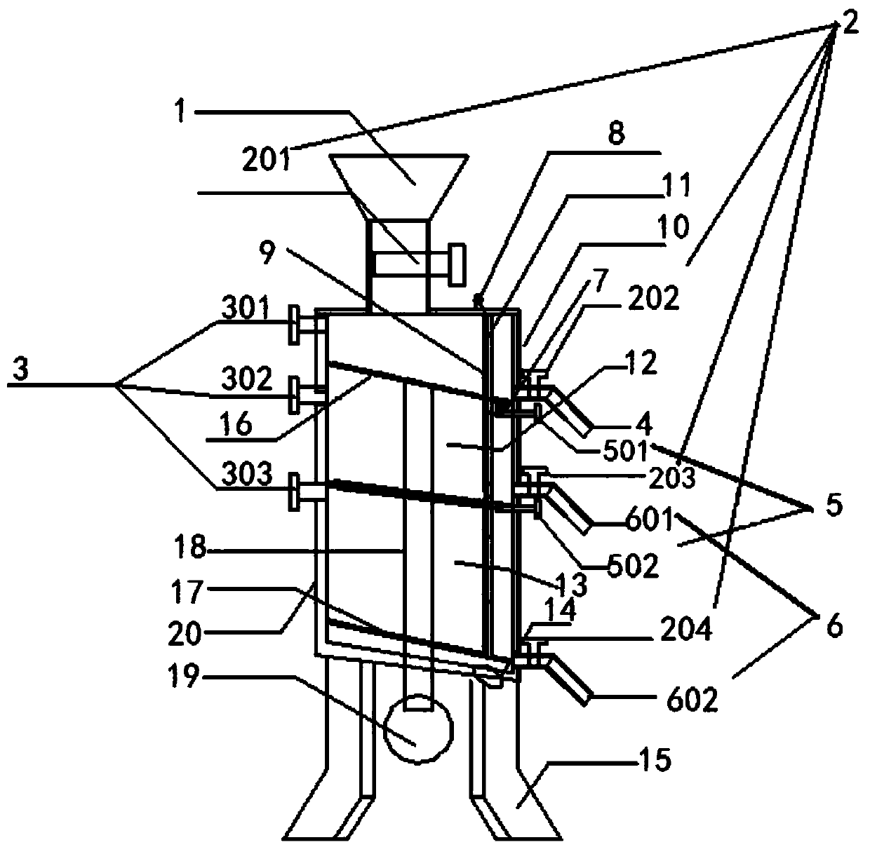
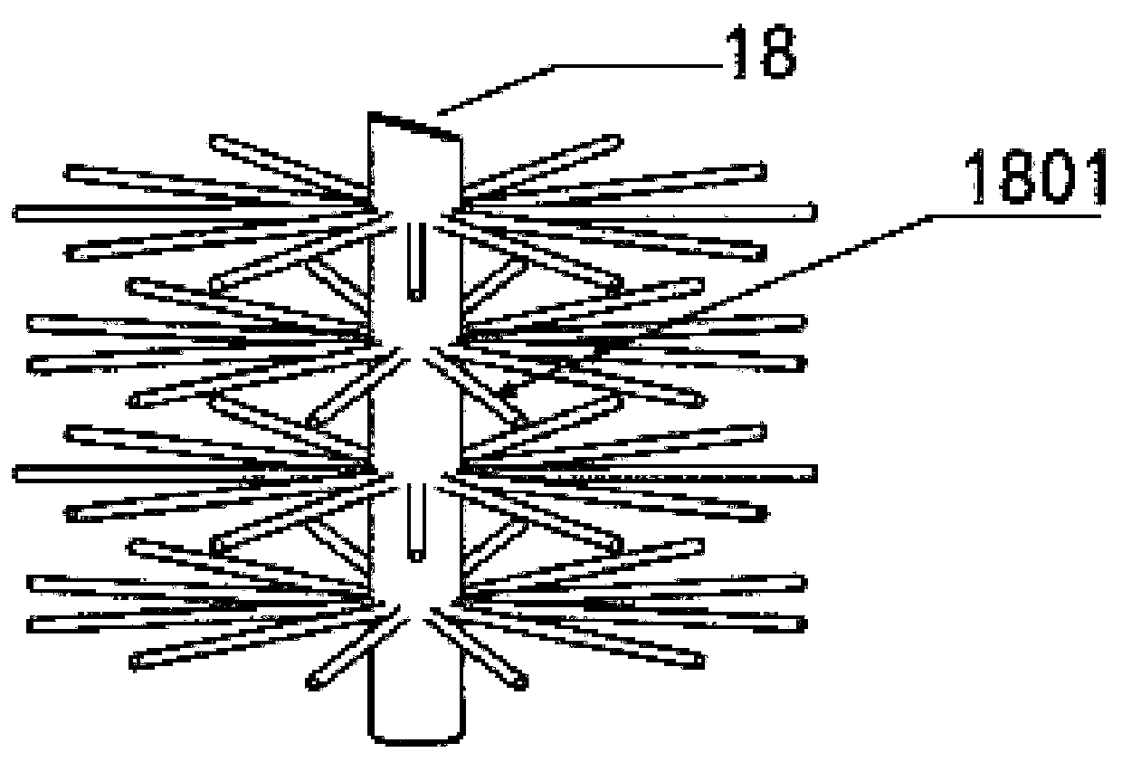
[0050] Such as figure 1 As shown, the grease waste treatment device used in the present invention includes a treatment box, an aeration system, a shaft system 18 , a central shaft drive system 19 and a temperature control system 20 , and the treatment box is installed on the bottom bracket 15 . In order to facilitate a better understanding of the present invention, the number of partitions will be described as two in th...


PUM


Abstract

The invention discloses a grease waste liquid treatment device. The treatment device comprises a treatment box body, an aeration system, a rotating shaft system and a central rotating shaft driving system, an inner cavity of the treatment box body is divided into an oil-water separation cavity and a multi-stage waste liquid treatment cavity, and the treatment device can be used for carrying out aerobic treatment, anaerobic treatment or anaerobic and aerobic composite treatment on oil-removed waste liquid after oil-water separation according to requirements. The internal structure of the treatment device is reasonably improved; the oil-water separation effect of the grease waste liquid is enhanced based on the gravity-air floatation principle; meanwhile, a biological treatment function is integrated; aerobic treatment, anaerobic treatment or anaerobic and aerobic composite treatment of the deoiling waste liquid obtained after oil-water separation can be respectively realized as required; resource utilization and environmental protection of the grease waste liquid are facilitated, the purposes of simplifying equipment and reducing treatment cost are achieved while high efficiency isachieved, and the method is particularly suitable for common families, catering merchants of various scales, central kitchens and other scenes.

Description

technical field [0001] The invention belongs to the technical field of grease waste liquid treatment, and in particular relates to a grease waste liquid treatment device for separating oil and water from kitchen grease waste liquid and biologically treating the oil-removing liquid phase to discharge standards. Background technique [0002] With the rapid development of my country's urbanization process and the improvement of people's living standards, the development of the catering industry has been greatly promoted, and a large amount of kitchen waste has also been generated. Due to the particularity of the nature of kitchen waste, a series of social and environmental problems will arise if it is not treated effectively. [0003] Kitchen oil waste has become an important factor threatening human health. Kitchen oil waste liquid is extremely perishable and degenerate, emits stench, and spreads bacteria and viruses. There are many toxic substances such as (benzoflower, benz...

Claims


Application Information

Patent Timeline
Patent Type & Authority Applications(China)
IPC IPC(8): C02F9/14C02F101/34
CPCC02F1/24C02F1/40C02F3/30C02F3/34C02F3/347C02F9/00C02F2101/34C02F2301/10
Inventor 邱忠平唐建陈帝霖王东梅王强柯佳闻刘洋
Owner SOUTHWEST JIAOTONG UNIV
Learn More