
Copper interconnection structure and preparation method thereof

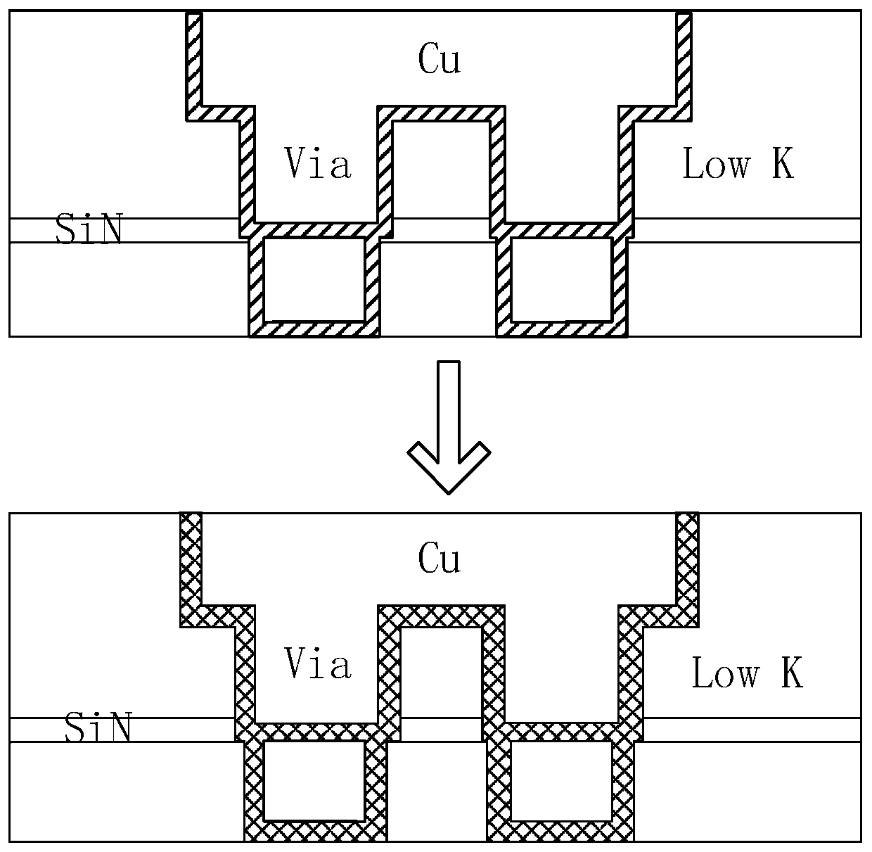
A copper interconnection structure and copper interconnection technology, applied in semiconductor/solid-state device manufacturing, electrical components, electrical solid-state devices, etc., can solve the problem of low utilization rate per unit area of ​​the chip

Inactive Publication Date: 2020-07-03
CSMC TECH FAB2 CO LTD
View PDF0 Cites 0 Cited by
  • Summary
  • Abstract
  • Description
  • Claims
  • Application Information

AI Technical Summary

Problems solved by technology

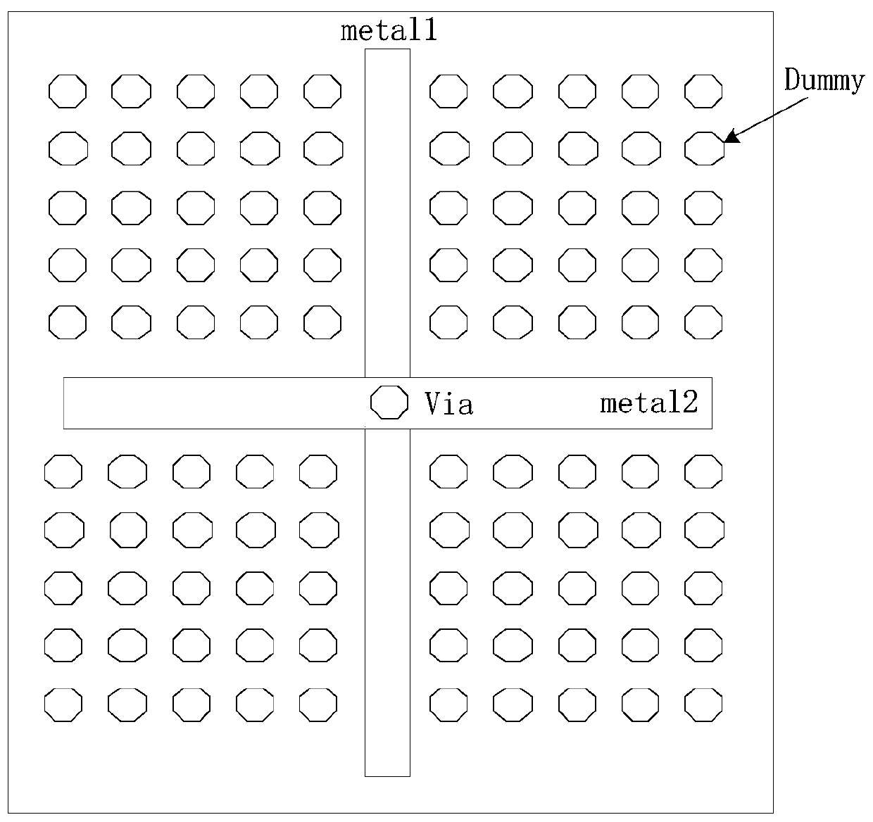
[0004] Based on this, it is necessary to provide a copper interconnection structure and its preparation method for the problem of low utilization per unit area in the chip caused by the setting of vacant patterns.

Method used


Image

  • Copper interconnection structure and preparation method thereof
  • Copper interconnection structure and preparation method thereof
  • Copper interconnection structure and preparation method thereof

Examples


Embodiment Construction

[0030] In order to make the above objects, features and advantages of the present invention more comprehensible, specific implementations of the present invention will be described in detail below in conjunction with the accompanying drawings. In the following description, numerous specific details are set forth in order to provide a thorough understanding of the present invention. However, the present invention can be implemented in many other ways different from those described here, and those skilled in the art can make similar improvements without departing from the connotation of the present invention, so the present invention is not limited by the specific implementations disclosed below.

[0031] Unless otherwise defined, all technical and scientific terms used herein have the same meaning as commonly understood by one of ordinary skill in the technical field of the invention. The terms used herein in the description of the present invention are for the purpose of descr...


PUM


Abstract

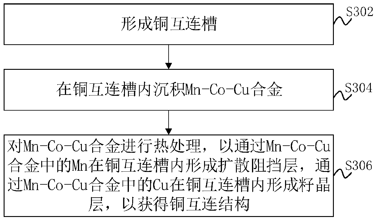
The invention relates to a copper interconnection structure and a preparation method thereof. The preparation method comprises the following steps: forming a copper interconnection groove; depositinga Mn-Co-Cu alloy in the copper interconnection groove; and carrying out heat treatment on the Mn-Co-Cu alloy, so that a diffusion barrier layer is formed in the copper interconnection groove through the Mn in the Mn-Co-Cu alloy, and a seed crystal layer is formed in the copper interconnection groove through the Cu in the Mn-Co-Cu alloy so as to obtain the copper interconnection structure. According to the invention, the diffusion impervious layer is formed by utilizing the Mn-Co-Cu alloy, so that water vapor and polar bond erosion can be effectively prevented, a large number of vacant patternsare not needed in circuit design, the utilization rate of unit area in a chip is greatly improved, and the limitation of an interconnection line failure mode on the design is broken through.

Description

technical field [0001] The invention relates to the technical field of semiconductors, in particular to a copper interconnection structure and a preparation method thereof. Background technique [0002] In the copper process of 90nm and below, in order to obtain better circuit response speed and shorter RC delay, the via (Via) inter-metal dielectric layer (IMD) generally uses a low dielectric constant (Low K) dielectric to Avoid excessive parasitic capacitance. However, the introduction of low-k dielectrics also brings about another common failure mode of interconnects (Inter-connect), that is, water vapor and polar bonds adsorbed by low-k dielectrics lead to oxidation of the barrier layer at the bottom of the via. , eventually causing the electrical drift of the interconnection line or device failure. [0003] This failure mechanism puts forward more requirements on the layout design of the interconnection line (Lay out). For example, when designing a circuit, more areas ...

Claims


Application Information

Patent Timeline
IPC IPC(8): H01L21/768H01L23/538
CPCH01L21/76843H01L21/76876H01L21/76883H01L21/76898H01L23/5384
Inventor 王德进周耀辉
Owner CSMC TECH FAB2 CO LTD
Learn More