

Up-flow hydrogenation reactor and application thereof
A hydrogenation reactor, upflow technology, applied in chemical instruments and methods, fixed bed hydrogenation treatment equipment, petroleum industry, etc., can solve problems affecting fluid distribution, adverse effects of reaction process, blockage of distributors, etc.
- Summary
- Abstract
- Description
- Claims
- Application Information
AI Technical Summary
Problems solved by technology
Method used
Image

Examples
Embodiment 1
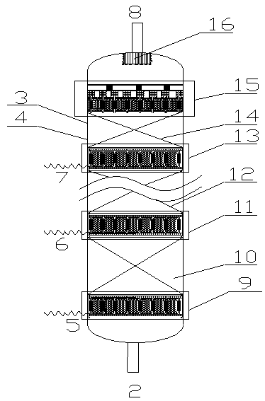
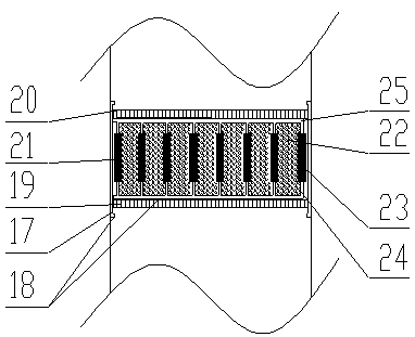
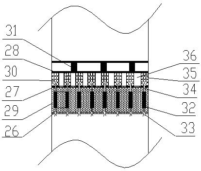
[0050] Using the upflow reactor described in the present invention (two catalyst beds and two floating hydrogen supply filter dust layers are arranged in the reactor), the raw material oil is introduced into the upflow reactor as the reactor feed (the reactor size is 100mm), the hydrogen is divided into two streams and respectively introduced into the first floating hydrogen supply dust filter layer and the first floating hydrogen supply dust filter layer, among which the membrane modules in the first floating hydrogen supply dust filter layer and the second floating hydrogen supply dust filter layer Hydrogen gas is dispersed into microbubbles of 50nm size. The first floating hydrogen supply dust filter layer 180mm, the first catalyst bed 400mm, the second floating hydrogen supply dust filter layer 100mm, the second catalyst bed 600mm, and the ceramic ball layer 100mm are sequentially filled in the reactor along the material flow direction; 1 The floating hydrogen supply dust ...
Embodiment 2
[0052] Using the upflow reactor described in the present invention, the raw material oil is introduced into the upflow reactor (reactor size is 200mm) as the reactor feed, and the hydrogen is divided into three streams and respectively introduced into the first floating hydrogen supply dust filter layer, the second Floating hydrogen supply dust filter layer, the third floating hydrogen supply dust filter layer, wherein the membrane components in the first floating hydrogen supply dust filter layer, the second floating hydrogen supply dust filter layer, and the third floating hydrogen supply dust filter layer disperse hydrogen Microbubbles with a size of 50nm; the reactor is filled with the first floating hydrogen supply dust filter layer 200, the first catalyst bed layer 700 mm, the second floating hydrogen supply dust filter layer 150 mm, and the second catalyst bed along the material flow direction. Layer 800 mm, the third floating hydrogen supply dust filter layer 100 mm, th...
PUM
 Abstract
Description
Claims
Application Information