Microwave drying device

A technology of microwave drying and microwave power, which is applied in the direction of heating device, drying solid materials, heating to dry solid materials, etc., which can solve the problems of large loss, scrapped wafers, and inability to completely remove moisture, etc.

Inactive Publication Date: 2020-07-07
INST OF MICROELECTRONICS CHINESE ACAD OF SCI
View PDF10 Cites 0 Cited by
  • Summary
  • Abstract
  • Description
  • Claims
  • Application Information

AI Technical Summary

Problems solved by technology

[0003] Traditional drying devices, such as centrifugal dryers, use centrifugal force to shake water out of the wafer to achieve drying. This method is effective for macroscopic structures, but it is difficult to completely remove the attached water in nano-patterned structures.
[0004] Another example is the nitrogen gun, which uses the ejected nitrogen to purge the structure on the wafer. This method is effective for the wide and shallow groove structure, but it is basically ineffective for the photoresist deep groove with high aspect ratio, and it is even possible These structures were blown down due to excessive blowing force
[0005] In addition, there are some composite drying devices, which add high-temperature drying modules on the basis of the above-mentioned devices, and use baking to dry. However, because the above-mentioned devices cannot completely remove moisture, during the baking process, due to the adhesion of The surface tension of the water in the graphic structure will inevitably cause the nano-pattern to collapse from the inside, causing the entire wafer to be scrapped and the loss is great

Method used


Image

  • Microwave drying device

Examples


Embodiment Construction

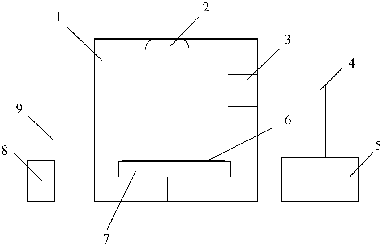
[0014] see figure 1 , a microwave drying device provided by an embodiment of the present invention, including a cavity 1, a UV curing lamp 2, a microwave coupler 3, a microwave transmission wire 4, a microwave power source 5, a slide table 7, a wafer 6, and a vacuum pump group 8 and catheter 9.

[0015] Wherein, the cavity 1 is generally made of aluminum material, and pure aluminum or aluminum alloy material can be used.

[0016] On the side wall of the cavity 1, a microwave coupler 3 is arranged, and the microwave power source 5 outside the cavity 1 is connected to the microwave coupler 3 through the microwave transmission wire 4, and the microwave power is delivered to the microwave coupler 3, and the microwave coupling The device 3 includes a microwave antenna for applying microwave power to the inside of the cavity 1 . The frequency range of the microwave power source 5 is 900MHz to 13GHz, preferably 915MHz to 10GHz, especially 915MHz to 3GHz; the rated output power rang...


PUM


Abstract

The invention provides a microwave drying device. The microwave drying device comprises a cavity, wherein a slide holder and a microwave coupler are arranged in the cavity; the slide holder is used for carrying a developed and replaced wafer; the microwave coupler is connected to a microwave power source through a microwave transmission wire; an opening is also formed in the cavity, and is connected to an external vacuum pump set through a guide pipe so as to discharge water vapor into the cavity to the exterior of the cavity; and an ultraviolet curing lamp is arranged in the cavity. The microwave drying device can effectively remove moisture on the wafer, and then solidifies nano-pattern structures; and the drying process does not cause the collapse of the structures.

Description

technical field [0001] The invention relates to the technical field of drying devices, in particular to a microwave drying device for curing nano-pattern structures on wafers. Background technique [0002] Modern integrated circuit technology continues to develop towards smaller feature sizes and larger wafer sizes, such as feature sizes entering 10 nanometers and wafer diameters larger than 12 inches, which poses greater challenges to the manufacturing process of microelectronic devices. Because in the manufacturing process of microelectronic devices, with the further reduction of the feature size and the further improvement of the structure complexity, the collapse of the nano-pattern structure on the wafer has become an increasingly serious problem. There are many reasons for the structure to collapse, such as being subjected to external forces, the stress of the structure itself, weaker structural materials, and surface tension during the drying process. Among them, due...

Claims


Application Information

Patent Timeline
Patent Type & Authority Applications(China)
IPC IPC(8): F26B3/347F26B23/08
CPCF26B3/347
Inventor 李勇滔景玉鹏
Owner INST OF MICROELECTRONICS CHINESE ACAD OF SCI
Why Eureka
Try Eureka