
Feed conditioning granulator

A granulator and tempering technology, which is applied in the direction of feed, mixer, mixer accessories, etc., can solve the problems of difficult discharge of materials, waste of steam, easy escape, etc., to improve the effect of conditioning and sterilization, and to avoid steam The effect of loss and avoiding heat loss

Pending Publication Date: 2020-07-10
河北鸿岳机械设备制造有限公司
View PDF0 Cites 2 Cited by
  • Summary
  • Abstract
  • Description
  • Claims
  • Application Information

AI Technical Summary

Problems solved by technology

The above-mentioned feed conditioning granulator has the following defects: First, because the filling degree of the material in the shell is only about two-thirds during the conditioning work, the steam is easy to run away at the inlet and outlet, resulting in The waste of steam increases the cost of steam in the production process; secondly, when the material is added into the charging port, the material is easy to accumulate at the feeding port, and the production efficiency is reduced; thirdly, the processed material is not easy to discharge from the discharge port Fourthly, since the two ends of the conditioner are provided with a feed inlet and a discharge port, not only the loss of steam is caused, but also the internal temperature of the conditioner is low and the temperature is uneven, the protein is thermally denatured and the bactericidal effect is poor, and the feed greatly reduced quality

Method used


Image

  • Feed conditioning granulator
  • Feed conditioning granulator

Examples


Embodiment Construction

[0012] The structure and operating principle of the feed conditioning granulator of the present invention will be further described in detail in conjunction with the accompanying drawings and specific embodiments.

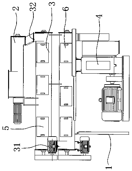
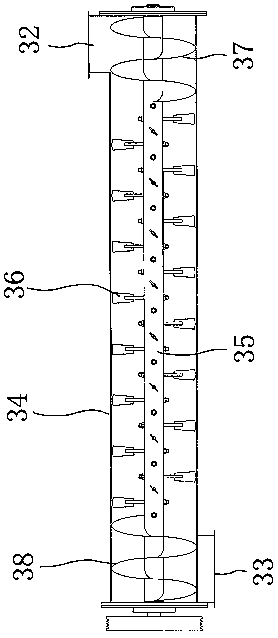
[0013] Such as figure 1 and figure 2 As shown, the structure schematic diagram of the feed conditioning granulator of the present invention, the feed conditioning granulator of the present invention includes a frame body 1 and a feeding mechanism 2 positioned at the top of the frame body, a conditioner 3 positioned below the feeding mechanism 2 and a The granulation mechanism 4 located under the conditioner 3 . The conditioner 3 includes a power mechanism 31, a housing 34 with a feed inlet 32 ​​and a discharge outlet 33, a stirring shaft 35 and a stirring fin 36 located on the stirring shaft, and the feed inlet 32 ​​and the discharge outlet 33 are located at On the sidewalls at both axial ends of the casing 34, a first spiral fin plate 37 is provided on the stir...


PUM


Abstract

The invention belongs to the technical field of feed production devices, and discloses a feed conditioning granulator. The feed conditioning granulator is mainly technically characterized by comprising a frame body, a feeding mechanism, a conditioner and a granulating mechanism, wherein the conditioner comprises a power mechanism, a shell with a feed port and a discharge port, a stirring shaft andstirring fins located on the stirring shaft; and spiral fin plates are arranged, opposite to the feed port and the discharge port, on the stirring shaft. After materials enter from the feed port, thefirst spiral fin plate on the stirring shaft located at the feed port pushes the materials forwards rapidly, feeding is more uniform, the materials and steam are fully mixed under the action of the stirring fins on the stirring shaft, and due to the fact that the first spiral fin plate and the second spiral fin plate are arranged at the two ends of the stirring shaft, the steam is sealed in the conditioner, the steam cost is saved, and the heat loss is avoided, so that the temperature is higher in the conditioning process, and the conditioning and sterilizing effects are greatly improved.

Description

technical field [0001] The invention belongs to the technical field of conditioning and granulating machinery, and in particular relates to a feed conditioning and granulating machine. Background technique [0002] Due to the low ability of most animals to digest starch, in the field of feed processing, powdery materials need to be matured. In the conditioner, saturated steam contacts with the material, and a large amount of heat is released when the surface of the powder is condensed. Absorption raises the temperature of the powder to 80-88°C, greatly increases the degree of gelatinization of the starch under the action of hydrothermal heat, and also promotes the thermal denaturation of the protein in the material. The denatured protein is easy to be enzymatically hydrolyzed, thereby improving The digestion and utilization rate of the pellet feed is improved, and the denatured protein can fully play the role of a binder, effectively bonding other components around it, and u...

Claims


Application Information

Patent Timeline
Patent Type & Authority Applications(China)
IPC IPC(8): A23N17/00B01F3/06B01F7/04B01F15/02B01J2/22A23L5/20B01F23/30
CPCA23N17/00A23N17/004A23N17/007B01J2/22A23L5/21A23V2002/00B01F23/30B01F27/70B01F35/754551B01F2101/18
Inventor 那小平位超
Owner 河北鸿岳机械设备制造有限公司
Learn More