Solar large-view-field high-resolution imaging telescope based on deformable secondary mirror

A high-resolution, telescope technology, applied in the field of solar adaptive optics telescopes, can solve problems such as limitations, difficult design of relay optical systems, and huge relay optical systems, so as to achieve sharing and improve wavefront detection and wavefront detection. The effect of pre-corrected signal-to-noise ratio and thermal radiation pollution suppression

Pending Publication Date: 2020-07-10
INST OF OPTICS & ELECTRONICS - CHINESE ACAD OF SCI
View PDF7 Cites 3 Cited by
  • Summary
  • Abstract
  • Description
  • Claims
  • Application Information

AI Technical Summary

Problems solved by technology

The existing surface adaptive optics telescope is limited by the relatively independent structure of the telescope and the adaptive optics system, and its typical high-resolution imaging field of view is only about 40 arcseconds to 1 arcminute (Deqing Ren, et al. Solar Ground- Layer Adaptive Optics, PUBLICATIONS OF THEASTRONOMICAL SOCIETY OF THE PACIFIC, 127:469–478, 2015; Ling Kong, et al. Prototype of solar ground layer adaptive optics at the 1m New Vacuum SolarTelescope, CHINESE OPTICS LETTERS, 14(10) 2016), unable to satisfy the non-scanning continuous large-field-of-view high-resolution observation of large solar active regions
The reason is that the existing surface adaptive optics telescope places the deformable mirror near the conjugate position of the pupil surface of the telescope’s back-end optical system, and faces the followi

Method used


Image

  • Solar large-view-field high-resolution imaging telescope based on deformable secondary mirror
  • Solar large-view-field high-resolution imaging telescope based on deformable secondary mirror
  • Solar large-view-field high-resolution imaging telescope based on deformable secondary mirror

Examples


Embodiment Construction

[0025] The present invention will be described in detail below in conjunction with the accompanying drawings and specific embodiments.

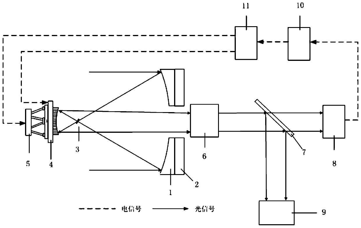
[0026] The illustration of this embodiment is as figure 1 As shown, a solar large-field-of-view high-resolution imaging telescope based on a deformable secondary mirror includes a primary mirror 1, a primary mirror temperature control system 2, a thermal field diaphragm 3, a deformable secondary mirror 4, a six-axis parallel mechanism 5, a central Following mirror group 6, beam splitter 7, large field of view wavefront detector 8, large field of view imaging detector 9, industrial computer 10, high voltage amplifier 11; wherein,

[0027] The solar light from outside the observation field of the telescope is reflected by the main mirror 1, and then reflected out of the telescope system by the thermal field diaphragm 3 located near the focal position of the main mirror of the telescope;

[0028] The sun’s rays from the observation field of the...


PUM


Abstract

The invention provides a solar large-view-field high-resolution imaging telescope based on a deformable secondary mirror. The telescope comprises a primary mirror, a primary mirror temperature controlsystem, a thermal field diaphragm, a deformation secondary mirror, a six-axis parallel mechanism, a relay reflector group, a large-field wavefront detector, a large-field imaging detector and the like, and the deformation secondary mirror and the six-axis parallel mechanism are combined to correct surface atmospheric turbulence wavefront distortion in real time. The size of a typical solar activity area is 1-2 angular minutes, a traditional self-adaptive optical telescope is limited by an isoplanatic area, a high-resolution imaging view field is only about 10 angular seconds, and the large-view-field high-resolution observation requirement of the solar activity area cannot be met. The objective of the invention is to realize high-resolution imaging with a larger field of view. According to the invention, the deformation secondary mirror and the six-axis parallel mechanism in the telescope primary optical system are used for correcting the atmospheric turbulence of the earth surface layer, high-resolution imaging of a field of view of more than 2 angular minutes can be realized on a large-aperture (2m-8m) solar telescope, and the overall real-time high-resolution imaging of a solaractivity area is satisfied.

Description

technical field [0001] The invention relates to a solar adaptive optics telescope, in particular to a solar large-field-of-view high-resolution imaging telescope based on a deformable secondary mirror. Background technique [0002] High-resolution imaging of the sun is of great significance for solar physics research, space environment monitoring and space weather forecasting. The field of view of a typical solar active region spans 1 to 2 arc minutes (Thomas R. Rimmele, SolarAdaptive Optics, Living Rev. Solar Phys.8:2, p68, 2011), and the study of its evolution requires a large field of view High-resolution monitoring to obtain the highly dynamic fine structure of the solar active region, and discover the dynamic origin of solar flares and coronal mass ejections and other solar eruptive activities. However, the high-resolution imaging field of view of traditional solar adaptive optics telescopes is limited by the halo region of the atmosphere, which is only about 10 arcsec...

Claims


Application Information

Patent Timeline
IPC IPC(8): G02B23/02G02B26/00G02B26/06
CPCG02B23/06G02B26/007G02B26/06
Inventor 饶长辉郭友明顾乃庭樊新龙孔林张兰强鲍华饶学军王佳英
Owner INST OF OPTICS & ELECTRONICS - CHINESE ACAD OF SCI
Why Eureka
Try Eureka