Small projection optical assembly suitable for near-to-eye display and projection optical system

A technology of projection optical system and near-eye display, which is applied in the field of projection systems, can solve the problems that the compactness of the waveguide near-eye display system cannot be further improved, the volume and weight are difficult to control, and the image cannot be optically enlarged, so as to achieve small volume and high optical performance, The effect of compact structure and reduced volume

Active Publication Date: 2020-07-10
BEIJING NEDPLUSAR DISPLAY TECH CO LTD
View PDF17 Cites 3 Cited by
  • Summary
  • Abstract
  • Description
  • Claims
  • Application Information

AI Technical Summary

Problems solved by technology

Due to the limitations of the optical principle, the flat waveguide element cannot provide any optical power and cannot optically magnify the image. Therefore, the performance of the projection part largely determines the quality of the displayed image of the waveguide near-eye display system. At present, The projection part requires more independent optical components, such as lenses, to improve the optical imaging quality, which makes it difficult to control the volume and weight, and cannot further improve the compactness of the waveguide near-eye display system

Method used


Image

  • Small projection optical assembly suitable for near-to-eye display and projection optical system
  • Small projection optical assembly suitable for near-to-eye display and projection optical system
  • Small projection optical assembly suitable for near-to-eye display and projection optical system

Examples


no. 1 example

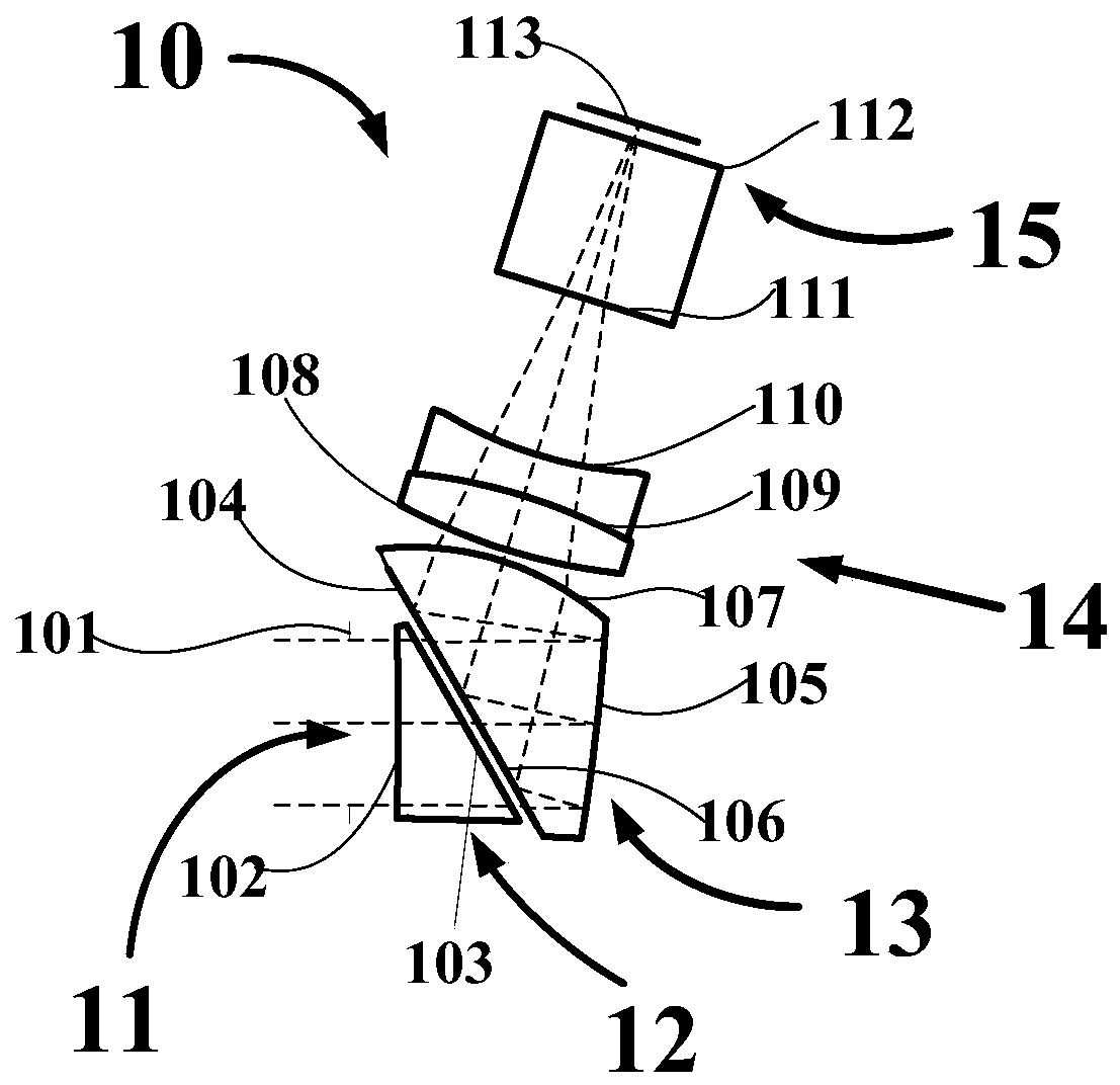
[0029] According to the projection optical assembly of the first embodiment of the present invention, the optical path is as follows figure 1 shown. The schematic image source 15 is realized with an LCoS microdisplay, and the image source 15 provides image light to the projection optical assembly. The image light passes through the lens group 14, the off-axis catadioptric prism 13, and the wedge prism 12, and then reaches the exit pupil Plane 11. According to the use of the projection optical assembly of the present invention, the image light passing through the projection optical assembly is coupled to a predetermined waveguide optical sheet at the exit pupil plane 11 .

[0030] In the first embodiment, as figure 1 As shown, the lens group 14 is formed in the form of a cemented lens, comprising a negative lens near the image source side, and a positive lens cemented to the negative lens. Preferably, the negative lens is formed by having a relatively high refractive index an...

no. 2 example

[0057] According to the second embodiment of the present invention, a similar projection optics assembly is used as in the first embodiment of the present invention, but with an OLED type microdisplay as the image source 25, such as Figure 6 shown.

[0058] According to the projection optical assembly of the second embodiment of the present invention, compared with using the LCoS type microdisplay as the image source, the OLED type microdisplay is a self-luminous device, which does not need an additional illumination light path for illumination, simplifies the complexity of image light formation, and The entire projection optics can be further reduced in weight because no additional lighting system is required.

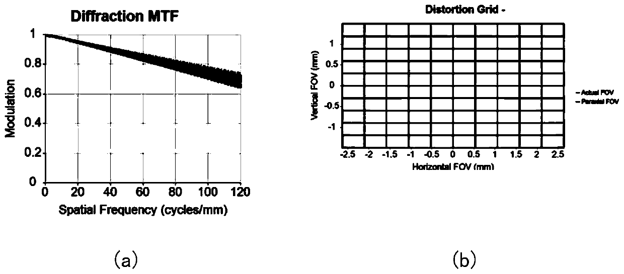
[0059] Figure 6A (a) shows the optical modulation transfer function (MTF) of the projection optics, Figure 6A (b) shows the corresponding distortion. Compared with the first embodiment, the system has similar optical performance, and also the maximum outer diame...

no. 3 example

[0075] According to the third embodiment of the present invention, the difference between this embodiment and the first embodiment is that this embodiment uses a MEMS (Micro Electromechanical System, Micro Electro Mechanical System) laser scanning mirror as an image source.

[0076] Compared with using OLED type microdisplay as image source, MEMS laser scanning mirror has high power, which can effectively improve the display brightness of image light; compared with using LCoS type microdisplay as image source, using MEMS laser scanning mirror as image source can The illumination light path including the shaping lens is omitted, further effectively reducing the weight of the projection optical system, and the light efficiency of the laser is also higher than that of the LED.

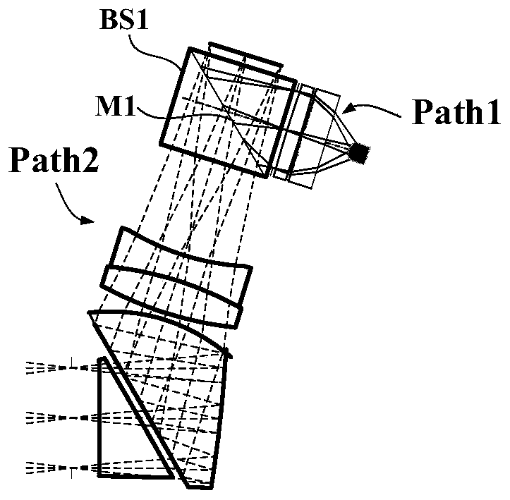
[0077] Figure 7 (a) shows the projection optical assembly of the third embodiment of the present invention and the optical path of the projection optical system using it, wherein the projection optical a...


PUM


Abstract

The invention provides a small projection optical assembly suitable for near-to-eye display. The assembly comprises a lens group which is used for correcting aberration in a system, such as chromaticaberration; a prism which is used for correcting off-axis aberration and deflection optical axis angle in the system; a wedge angle prism which is used for slightly controlling the angle of the optical axis relative to the exit pupil plane; and a predetermined waveguide sheet into which image light passing through the projection optical assembly is coupled in the exit pupil plane. The projection optical assembly is small in size, compact in structure and excellent in optical performance, and the vertical axis size does not exceed 7 mm.

Description

technical field [0001] The invention relates to a projection system in the optical field, in particular to a small projection optical assembly and a projection optical system suitable for near-eye displays. Background technique [0002] The concept of augmented reality (augmented reality, AR) technology has been widely spread. This technology can provide users with additional superimposed information while not blocking the normal observation of the human eye, effectively expanding the information capacity visible to the human eye. Education, medical treatment, entertainment and other fields all have broad application prospects. As an important device for realizing augmented reality, the research and development of transmissive head-mounted near-eye displays has become a hot topic nowadays. At present, companies such as EPSON, Google, Microsoft, etc. have invested in the research and development of related technologies and launched related products such as ESPON-BT series, G...

Claims


Application Information

Patent Timeline
Patent Type & Authority Applications(China)
IPC IPC(8): G03B21/00G02B7/02G02B7/18G02B27/00G02B27/01G02B27/09G02B27/28
CPCG03B21/006G03B21/008G02B27/0025G02B7/025G02B7/1805G02B27/0955G02B27/0101G02B27/283
Inventor 程德文陈海龙王其为侯起超
Owner BEIJING NEDPLUSAR DISPLAY TECH CO LTD
Why Eureka
Try Eureka