Wheel hub motor and wheel hub motor heat dissipation system

A technology of in-wheel motor and motor shaft, which is applied in the direction of electromechanical devices, electrical components, electric components, etc., can solve the problems that heat cannot be discharged in time and effectively, large heat of coil winding and motor casing, etc., to improve heat exchange efficiency. , save material, avoid the effect of interference

Active Publication Date: 2020-07-14
HENAN UNIV OF SCI & TECH
View PDF5 Cites 15 Cited by
  • Summary
  • Abstract
  • Description
  • Claims
  • Application Information

AI Technical Summary

Problems solved by technology

[0005] The purpose of the present invention is to provide a wheel hub motor to solve the problem that in the prior art, the heat generated by the coil winding of the stator at both axial ends of the hub motor cannot be discharged in time and effectively, and it is easy to generate heat between the coil winding and the motor housing. The technical problem of large heat; the purpose of the present invention is also to provide a hub motor heat dissipation system to solve the problem that the heat generated by the coil winding of the stator at the axial ends of the hub motor in the prior art cannot be discharged in a timely and effective manner, and it is easy to in-line The technical problem of large heat generation between the coil winding and the motor housing

Method used


Image

  • Wheel hub motor and wheel hub motor heat dissipation system
  • Wheel hub motor and wheel hub motor heat dissipation system
  • Wheel hub motor and wheel hub motor heat dissipation system

Examples


specific Embodiment 1

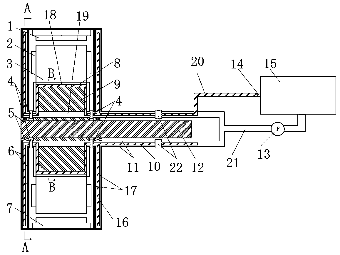
[0077] Such as figure 1 As shown, the hub motor cooling system includes the hub motor and the cooling water tank 15, a first pipeline 20 and a second pipeline 21 are arranged between the hub motor and the cooling water tank 15, one end of the first pipeline 20 is connected to the cooling water tank 15, and the other is connected to the cooling water tank 15. One end is connected to the liquid inlet pipeline of the hub motor through the outer rotary joint 22 , one end of the second pipeline 21 is connected to the cooling water tank 15 , and the other end is connected to the liquid outlet pipeline of the hub motor through the outer rotary joint 22 . Wherein, the first pipeline 20 is provided with a water tank valve 14 , and the second pipeline 21 is provided with a circulation pump 13 .

[0078] In this embodiment, one end of the first pipeline 20 connected to the outer rotary joint 22 and one end of the second pipeline 21 connected to the outer rotary joint 22 are ring structur...

specific Embodiment 2

[0091] The difference from the specific embodiment 1 is that in embodiment 1, a heat-conducting copper bar is provided on the outer peripheral surface of the stator liquid inlet channel to improve the heat exchange efficiency. The copper bar is coated with a heat conduction layer on the outer peripheral surface of the stator liquid inlet channel to improve heat exchange efficiency.

specific Embodiment 3

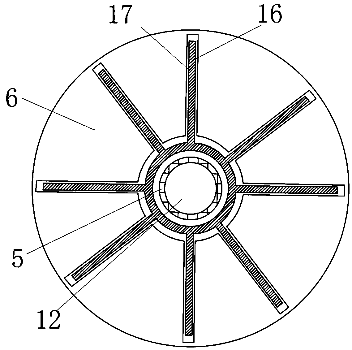
[0093] The difference from the specific embodiment 1 is that in embodiment 1, a blind hole is provided on the motor housing 6, and the blind hole extends radially along the motor shaft 12, and the end of the blind hole away from the motor shaft 12 is a blind end, and the blind hole constitutes a The liquid outlet channel of the casing. In this embodiment, a blind hole is provided on the motor casing, and a pipeline with one end closed and one end open is arranged in the blind hole, and the pipeline in the blind hole constitutes the casing liquid outlet channel.


PUM


Abstract

The invention relates to a wheel hub motor and a wheel hub motor heat dissipation system. The wheel hub motor comprises a motor shaft, a motor shell, a stator and a rotor; the motor shaft is fixedlyconnected with the suspension of a vehicle; the motor shell is rotationally assembled on the motor shaft; the motor shell comprises an axial end cover part; the stator is arranged in the motor shell and fixedly arranged on the motor shaft; the stator comprises a coil winding; and the rotor is fixedly arranged in the motor shell and surrounds the stator. The wheel hub motor further comprises a shell cooling channel; the shell cooling channel is arranged in the axial end cover part and is used for cooling the coil winding; the shell cooling channel is connected with an external liquid inlet channel and an external liquid outlet channel; and the external liquid inlet channel and the external liquid outlet channel are connected with a circulating liquid supply device so as to achieve circulating liquid supply cooling. It can be ensured that the wheel hub motor is always kept in a normal temperature range, and the service life of the wheel hub motor is prolonged.

Description

technical field [0001] The invention relates to a hub motor and a cooling system for the hub motor. Background technique [0002] With the development of new energy electric vehicles and hybrid technology, compact and efficient hub motors are gradually being favored. The pursuit of vehicle power performance has led to higher and higher power hub motors, so the heat generated by hub motors will also increase. If the generated heat cannot be discharged in time and effectively, it will cause the internal heat of the motor to accumulate and generate high temperature. If the internal temperature of the hub motor is too high, the insulation of the coil winding will be damaged and the permanent magnet will be irreversibly demagnetized. This will greatly reduce the The life of the wheel-rail motor affects the safety of the car. Therefore, the internal temperature of the wheel hub motor must be controlled within the allowable range. [0003] The Chinese patent with authorized notifi...

Claims


Application Information

Patent Timeline
Patent Type & Authority Applications(China)
IPC IPC(8): H02K1/20H02K5/20H02K5/04H02K9/19H02K9/22H02K7/00
CPCH02K1/20H02K5/04H02K5/20H02K7/006H02K9/19H02K9/22
Inventor 周志刚杨文豪李争争孟祥明
Owner HENAN UNIV OF SCI & TECH
Why Eureka
Try Eureka