Heat pump integrated fuel cell automobile heat management system with waste heat utilization function

A thermal management system, fuel cell technology, applied in fuel cells, battery/fuel cell control devices, electric vehicles, etc. The effect of reducing thermal efficiency, improving low-temperature driving range, and improving the range of use

Active Publication Date: 2020-07-17
JILIN UNIV
View PDF18 Cites 18 Cited by
  • Summary
  • Abstract
  • Description
  • Claims
  • Application Information

AI Technical Summary

Problems solved by technology

[0003] The fuel cell start-up problem is one of the bottlenecks in the development of the industry. When the start-up temperature of the fuel cell is below 0°C, the water generated by the fuel cell reaction may form ice, covering the reaction gas flow channel, the catalytic layer and the membrane electrode, thus hindering the development of the fuel cell. The progress of the electrochemical reaction
At the same time, due to the volume expansion of the membrane electrode icing, the electrode structure is damaged and the performance of the fuel cell is reduced; the low-temperature cold start of the fuel cell is mostly heated by external liquid, which consumes a large amount of electric energy of the battery pack and has low thermal efficiency.
[0004] For the low-temperature heating of the fuel cell passenger compartment, most of them can only use the PTC heating system because there is no heat supply from the high-temperature engine coolant of traditional fuel vehicles, which has high reliability, but its heating coefficient is low and energy consumption is large; Realize the integration of heating and cooling, its heating coefficient COP is greater than 1, which is about twice the heating coefficient of the PTC system, and the energy consumption is small; but the ordinary heat pump air conditioner uses a single environmental heat source heat pump, and the heating efficiency is reduced in low temperature and severe cold , the external heat exchanger is prone to frost, which cannot meet the requirements of efficient and reliable operation, and still needs PTC assistance, which increases the energy consumption of the whole vehicle; in addition, the waste heat of the motor and the waste heat of the fuel cell are not effectively utilized at low temperatures, and the energy utilization rate is reduced

Method used


Image

  • Heat pump integrated fuel cell automobile heat management system with waste heat utilization function
  • Heat pump integrated fuel cell automobile heat management system with waste heat utilization function
  • Heat pump integrated fuel cell automobile heat management system with waste heat utilization function

Examples


Embodiment 1

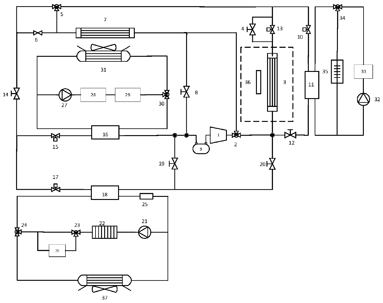
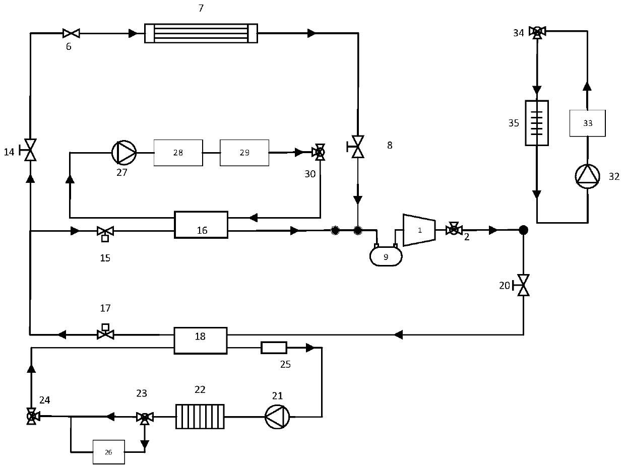
[0067] Embodiment 1, the direct cold start function of the fuel cell 22 heated by the heat pump cycle:

[0068] Such as figure 2 As shown, in the heat pump circulation circuit, adjust the No. 1 reversing valve 2 to connect to the evaporator 3, open the No. 2 shut-off valve 20, No. 3 shut-off valve 8, and No. 6 shut-off valve 14, and keep No. 1 shut-off valve 19, No. No. 12 shut-off valve and No. 5 shut-off valve 4 are closed, No. 1 electronic expansion valve 17 is fully open, No. 2 electronic expansion valve 15, No. 3 electronic expansion valve 13, and No. 4 electronic expansion valve 10 are in the closed state without power supply; Connected compressor 1, No. 1 reversing valve 2, No. 2 stop valve 20, No. 1 plate heat exchanger 18, No. 1 electronic expansion valve 17, No. 6 stop valve 14, throttling pipe 6, condenser 7, and three No. shut-off valve 8 and dryer 9 form the direct cold start cycle of fuel cell 22.

[0069] The refrigerant passes through the compressor 1 to for...

Embodiment 2

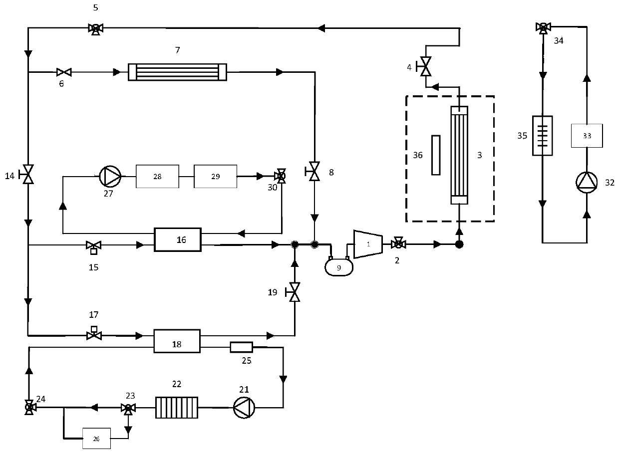
[0073] Embodiment 2 provides the function of the heat pump to recycle waste heat from the motor cycle or the fuel cell 22 cycle to heat the passenger compartment:

[0074] Such as image 3 As shown, in the heat pump circulation circuit, the flow direction of No. 1 reversing valve 2 is adjusted so that it is connected to the evaporator 3, No. 1 shut-off valve 19, No. 2 shut-off valve 20, No. 4 shut-off valve 12, and No. 6 shut-off valve 14 are closed. No. 3 shut-off valve 8 and No. 5 shut-off valve 4 are opened, and No. 2 reversing valve 5 is adjusted to connect to No. 6 shut-off valve 14; compressor 1, No. 1 reversing valve 2, evaporator 3, and No. 5 are connected sequentially. Stop valve 4, No. 2 reversing valve 5, throttling pipe 6, condenser 7, No. 3 stop valve 8, and dryer 9 form an ambient heat source heat pump cycle.

[0075] The refrigerant passes through the compressor 1 to form a high-temperature, high-pressure refrigerant, and then enters the evaporator 3 through th...

Embodiment 3

[0079] Embodiment 3, the function of heating the passenger compartment by only using the motor to circulate waste heat:

[0080] If the ambient temperature is low and the efficiency of heating the passenger compartment with an ambient heat source is very low, then close the No. 3 shut-off valve 8, and all the refrigerant passing through the No. 2 reversing valve 5 will pass through No. 6 shut-off valve 14 and No. 2 electronic expansion valve 15 to enter the No. 1 valve. The two-plate heat exchanger 16 forms a motor single heat source heat pump cycle.


PUM


Abstract

The invention discloses a heat pump integrated fuel cell automobile heat management system with a waste heat utilization function. The heat pump integrated fuel cell automobile heat management systemcomprises a heat pump circulation loop, a motor circulation loop, a fuel cell circulation loop and a battery pack circulation loop. The heat pump circulation loop is connected with other circulation loops through a plurality of plate heat exchangers to form the integrated heat management system, is connected with the fuel cell circulation loop through a first plate heat exchanger, is connected with the motor circulation loop through a second plate heat exchanger and is connected with the battery pack circulation loop through a third plate heat exchanger. Through the heat pump integrated heat management system, the heat pump cycle can utilize the environment or other heat sources to assist in heating the fuel cell to realize low-temperature cold start; a multi-heat-source heat pump air conditioner is composed of a fuel cell and motor circulating waste heat, the defect that the energy efficiency value of a heat pump is low at low temperature is overcome, and frosting of an external heatexchanger can be avoided.

Description

technical field [0001] The invention belongs to the field of fuel cell vehicles, and relates to a fuel cell vehicle integrated thermal management system, in particular to a heat pump integrated fuel cell vehicle thermal management system with waste heat utilization. Background technique [0002] The proton exchange membrane fuel cell directly undergoes a chemical reaction inside the battery, thereby converting chemical energy into electrical energy. The product is only water and heat. It has the advantages of high energy conversion rate, high power density, and zero emissions. It is widely used in automobiles, power generation systems and Power system and other aspects have broad application prospects. In actual operation, the suitable operating temperature of many low-temperature proton exchange membrane fuel cells is 60°C to 80°C. Most of the heat of the fuel cell comes from the catalyst layer on the cathode side, and about 5% of the waste heat can be dissipated through th...

Claims


Application Information

Patent Timeline
IPC IPC(8): B60L58/31B60L58/33B60L58/34B60H1/00B60H1/03H01M8/04029H01M8/04223
CPCB60L58/31B60L58/33B60L58/34B60H1/00278B60H1/00271B60H1/00392B60H1/034H01M8/04029H01M8/04268Y02T90/40
Inventor 于远彬黄世佩蒋俊宇闵海涛
Owner JILIN UNIV
Why Eureka
Try Eureka