Laser cladding powder feeder

A technology of laser cladding and powder feeder, applied in metal material coating process, coating and other directions, can solve the problems that manual operation cannot reach expectations, affect laser cladding processing, and block the powder feeding port of powder feeding nozzle. The effect of avoiding blockage, cooling in time, and reducing material waste

Pending Publication Date: 2020-07-17
XINJIANG HUIXIANG LASER TECH
View PDF0 Cites 1 Cited by
  • Summary
  • Abstract
  • Description
  • Claims
  • Application Information

AI Technical Summary

Problems solved by technology

[0004] The purpose of the present invention is to provide a laser cladding powder feeder to solve the problem that manual operation cannot achieve the expected effect during the mixing process proposed in the above background technology, thus affecting the yield of parts after laser cladding, and Too much mixing is easy to cause waste. In laser cladding, the temperature around the laser focus will be quite high. When the temperature of the powder feeding nozzle is close to the melting point of the powder, the powder feeding port of the powder feeding nozzle will be blocked, which affects the laser cladding process.

Method used


Image

  • Laser cladding powder feeder
  • Laser cladding powder feeder
  • Laser cladding powder feeder

Examples


Embodiment Construction

[0026] The following will clearly and completely describe the technical solutions in the embodiments of the present invention with reference to the accompanying drawings in the embodiments of the present invention. Obviously, the described embodiments are only some, not all, embodiments of the present invention. Based on the embodiments of the present invention, all other embodiments obtained by persons of ordinary skill in the art without creative efforts fall within the protection scope of the present invention.

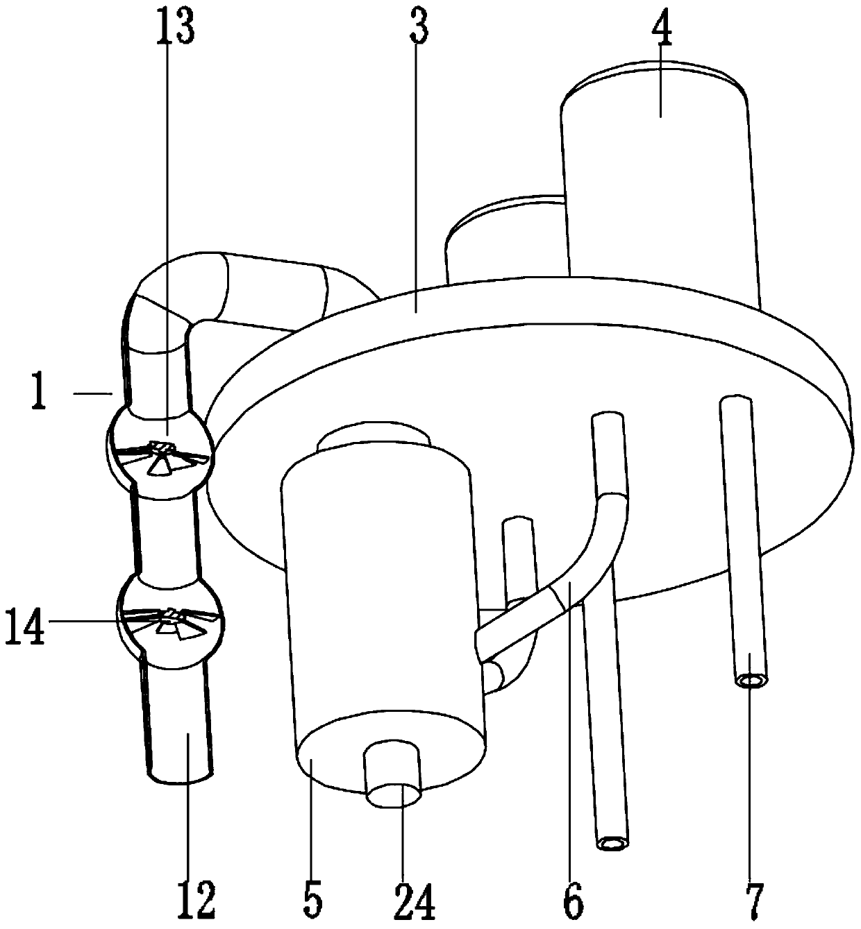
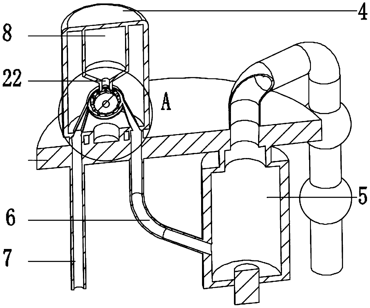
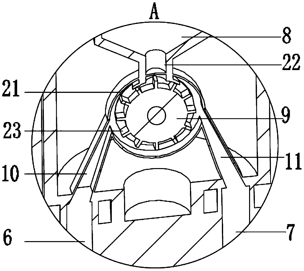
[0027] see Figure 1-5 , the present invention provides a technical solution:

[0028] A powder feeder for laser cladding, including a powder storage device 1 and a powder feeding head 2, the powder storage device 1 includes a fixed plate 3, a group of storage cylinders 4 are fixedly installed on the top of the fixed plate 3, and a mixing cylinder is fixedly connected to the bottom of the fixed plate 3 5. The storage cylinder 4 is connected to the mixing cylinder ...


PUM


Abstract

The invention discloses a laser cladding powder feeder, and belongs to the technical field of laser cladding. The laser cladding powder feeder comprises a powder storage device and a powder feeding head, wherein the powder storage device comprises a fixed disc, a group of storage cylinders are fixedly mounted at the top of the fixed disc, a mixing cylinder is fixedly connected to the bottom of thefixed disc, the storage cylinders communicate with the mixing cylinder through mixing pipes, powder discharging hoppers are fixedly connected to the middle of the storage cylinders, rotating wheels are arranged below the powder discharging hoppers, a mixed material pipe and a powder feeding pipe are fixedly arranged on the side wall of each rotating wheel, the top of the mixing cylinder communicates with an output pipe, a homogenizing pipe is fixedly connected to the middle of the output pipe, homogenizing fan blades are fixedly installed in the middle of the homogenizing pipe, the output pipe communicates with a powder feeding head, the powder feeding head comprises a water cooling sleeve, a protective sleeve and a powder feeding sleeve, a powder feeding channel is arranged between the powder feeding sleeve and the protective sleeve, an air curtain channel is arranged between the protective sleeve and the water cooling sleeve, and a water cooling cavity is formed in middle of the water cooling sleeve. According to the laser cladding powder feeder, with the arrangement of the multiple groups of the powder feeding paths, the flexible material utilization is achieved, the material waste is reduced, the mixing is simple and convenient, the ratio is accurate, the cladding quality is improved, and the powder sintering blocking is avoided to a certain extent.

Description

technical field [0001] The invention relates to the technical field of laser cladding, in particular to a laser cladding powder feeder. Background technique [0002] Laser cladding is a new surface modification technology. It adds cladding materials to the surface of the substrate and uses a high-energy-density laser beam to fuse it together with the thin layer on the surface of the substrate. The main method is to place the selected coating material on the surface of the substrate to be clad in different ways, and then irradiate it with laser to make it melt with a thin layer on the surface of the substrate at the same time, and after rapid solidification, the dilution degree is extremely low, and it is formed with the substrate. Metallurgically bonded surface coatings. Its purpose is to improve the wear resistance, corrosion resistance, heat resistance, oxidation resistance and electrical properties of the substrate surface, so as to achieve the modification and repair of...

Claims


Application Information

Patent Timeline
Patent Type & Authority Applications(China)
IPC IPC(8): C23C24/10
CPCC23C24/10
Inventor 朱金娇徐峰孙传武许娇成李蓉黄黎明李晓兵
Owner XINJIANG HUIXIANG LASER TECH
Why Eureka
Try Eureka