Turnout position detection device and system

A technology of detection device and turnout, applied in the direction of measurement device, electromagnetic measurement device, electromagnetic/magnetic position measurement, etc., can solve the problems of hidden safety hazards, low reliability and low safety factor of relays, and achieve high safety and improve safety. The coefficient is not high, the effect of improving safety

Pending Publication Date: 2020-07-17
王先宏
View PDF0 Cites 2 Cited by
  • Summary
  • Abstract
  • Description
  • Claims
  • Application Information

AI Technical Summary

Problems solved by technology

However, the existing detection device mainly has the following disadvantages: due to the dependence on the polarized relay using the AC power supply, when the relay fails to normally pull in or the response speed is delayed, it will cause potential safety hazards
[0004] In summary, the existing switch position detection devices have the problems of low safety factor and low reliability

Method used


Image

  • Turnout position detection device and system
  • Turnout position detection device and system
  • Turnout position detection device and system

Examples


Embodiment 1

[0033] Such as figure 1 As shown, the embodiment of the present invention provides a switch position detection device, including: a DC power supply group 100, a drive circuit 200 connected to the DC power supply group, and a position detection circuit 300 connected to the drive circuit.

[0034] In some embodiments, the DC power supply group includes a first power supply and a DC power supply.

[0035] In some embodiments, the voltage of the direct current power supply is 24V, and the voltage of the first power supply is 5V.

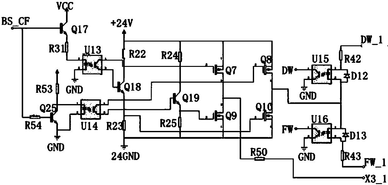
[0036] In some embodiments, such as figure 2 As shown, the driving circuit includes a positioning driving circuit and a reverse driving circuit; wherein, the positioning driving circuit includes triodes Q17, Q18, field effect transistors Q7, Q10, photoelectric isolator U13, and resistors R22, R23, R31; The base of Q17 is used as the signal input terminal, connected to the trigger signal BS_CF; the collector of Q17 is connected to the positive terminal o...

Embodiment 2

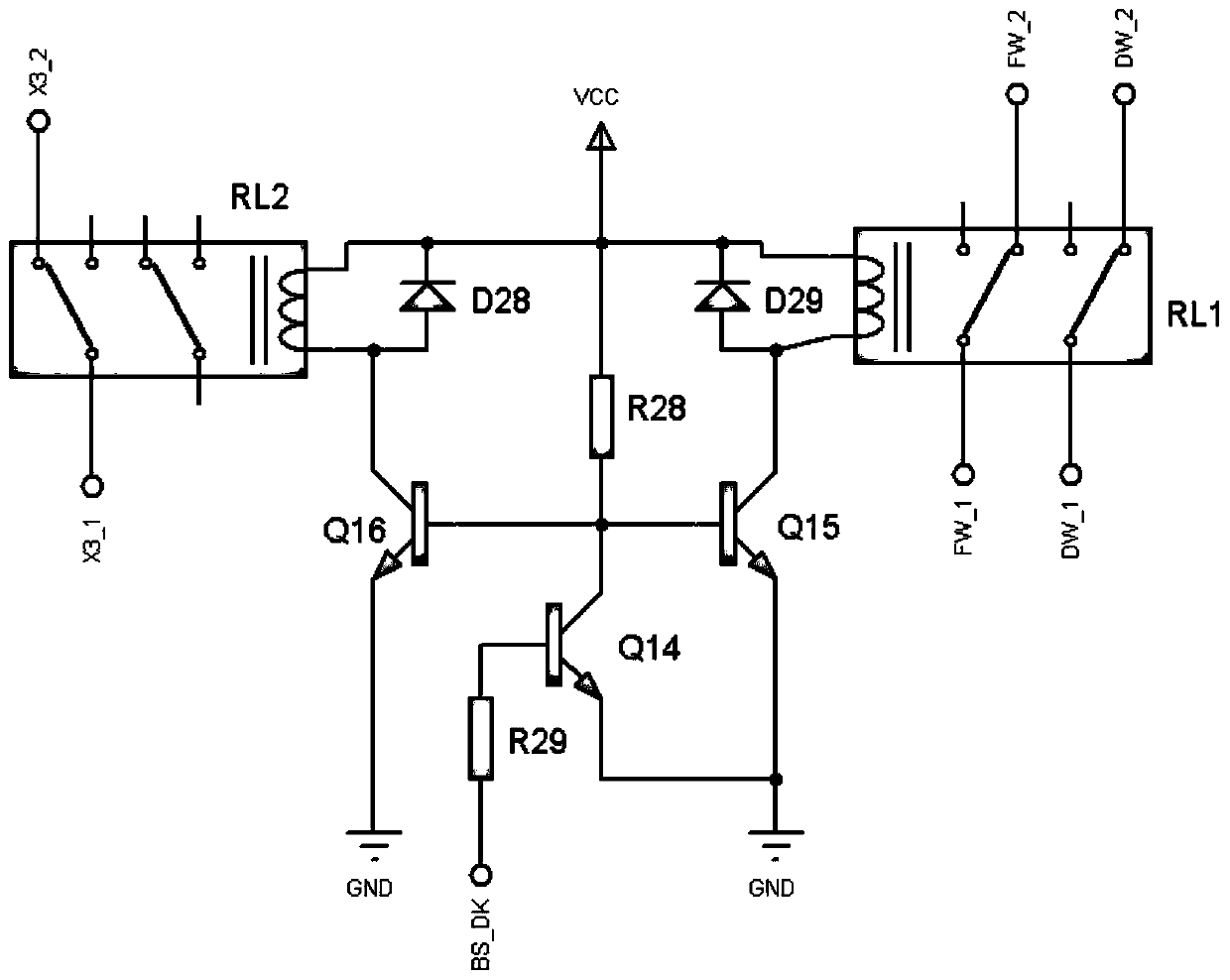
[0046] This embodiment provides a switch position detection device, which includes a trigger control circuit, a drive circuit, a position detection circuit and an electronic relay circuit;

[0047] Combine below Figure 2 to Figure 4 Each circuit of the device is described in detail respectively:

[0048] 1. Trigger control circuit:

[0049] The trigger signal adopts a periodically changing square wave signal, adopts an inversion circuit to obtain two opposite signals, and triggers the driving circuit to work.

[0050] The trigger signal is sent by the microprocessor (CPU) U21: AT89C51 chip P1.2 pin, and the trigger signal BS_CF is sent to the drive circuit.

[0051] It should be pointed out that the CPU can complete the logic programming processing and signal locking of the trigger signal;

[0052] Specifically, it has the following three functions, (1), the periodic change signal can be completed by the internal timer; (2), the "positioning operation" and "reverse bit ope...

Embodiment 3

[0076] An embodiment of the present invention provides a switch position detection system, including a switch machine and the switch position detection device according to any one of the foregoing embodiments.


PUM


Abstract

The embodiment of the invention provides a turnout position detection device and system, and relates to the field of railways, and the turnout position detection device comprises a DC power supply group, a drive circuit connected with the DC power supply group, and a position detection circuit connected with the drive circuit. Therefore, compared with the prior art that turnout position detectionis carried out by means of a polarization relay of an alternating-current power supply, the embodiment of the invention provides a technical scheme that uses A DC power supply group, the signal is more reliable and higher in safety, and the invention can improve the problems of lower safety coefficient and low reliability in the prior art, and improves the reliability and safety; the turnout position detection device realizes the function completed by a polarized relay in a point switch by adopting an electronic circuit, and also has the following advantages that the occupied space of electronic devices is smaller, the live plugging can be realized, and replacement is easy.

Description

technical field [0001] The invention relates to the field of switch detection, in particular to a switch position detection device and system. Background technique [0002] The switch machine refers to the important signal infrastructure equipment used to reliably change the position of the turnout, change the opening direction of the turnout, lock the tip rail of the turnout, and reflect the position of the turnout. It can well ensure driving safety, improve transportation efficiency, and improve the safety of driving personnel labor intensity. Since switch machines and turnouts are important components of railway track traffic, the position detection of switch machines and turnouts is very necessary for track safety. [0003] At present, the existing switch position detection devices mainly use polarized relays, which are used in the position detection applications of railway switch machine control. It is a half-wave DC power supply. If the direction of the power supply ...

Claims


Application Information

Patent Timeline
Patent Type & Authority Applications(China)
IPC IPC(8): G01B7/00H03K19/0175H03K19/003
CPCG01B7/003H03K19/003H03K19/00307H03K19/00315H03K19/017518H03K19/017536H03K19/017581
Inventor 王先宏李琦程相波许鹏王昕玥
Owner 王先宏
Why Eureka
Try Eureka