CSRR microstrip resonance sensor for measuring complex dielectric constant and application thereof

A complex permittivity, microstrip resonance technology, applied in the measurement of electrical variables, resistance/reactance/impedance, measurement devices, etc., can solve the problems of complex sample preparation process, expensive test equipment, complex sample preparation, etc. Sample preparation, light weight, small volume effect

Pending Publication Date: 2020-07-17
NORTH CHINA ELECTRIC POWER UNIV (BAODING)
View PDF0 Cites 21 Cited by
  • Summary
  • Abstract
  • Description
  • Claims
  • Application Information

AI Technical Summary

Problems solved by technology

In the free space method, the Gaussian microwave beam focused antenna is placed on one or both sides of the substance to be measured, and the antenna terminal is connected to a vector network analyzer to measure the attenuation and phase constant to realize the measurement of the dielectric constant. This measurement method can be used in a wide range The complex dielectric constant can be measured in the frequency range, but the measurement accuracy is not high and the test equipment is expensive; the transmission line method usually needs to place the substance to be tested inside the transmission line, such as waveguide, coaxial line, microstrip line, etc., by measuring the reflection coefficient and the transmission coefficient to obtain the complex permittivity. Compared with the free space method, the test cost of the transmission line method is lower, but the preparation of the sample is more complicated; the resonant cavity perturbation method is the most accurate microwave measurement method for measuring low-loss substances. The test sample is completely filled or partially filled into the cavity, and the dielectric properties of the material are obtained by measuring the resonant frequency and quality factor
The resonant cavity method can achieve high-accuracy measurement of dielectric constant in a narrow frequency range, but it also has the problem of complicated sample preparation process

Method used


Image

  • CSRR microstrip resonance sensor for measuring complex dielectric constant and application thereof
  • CSRR microstrip resonance sensor for measuring complex dielectric constant and application thereof
  • CSRR microstrip resonance sensor for measuring complex dielectric constant and application thereof

Examples


Embodiment Construction

[0031] In order to have a further understanding of the technical solution and beneficial effects of the present invention, the technical solution of the present invention and its beneficial effects will be described in detail below in conjunction with the accompanying drawings.

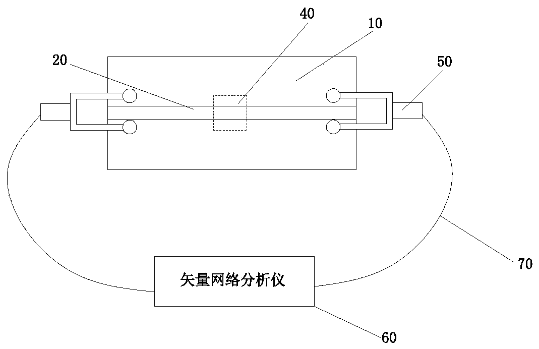
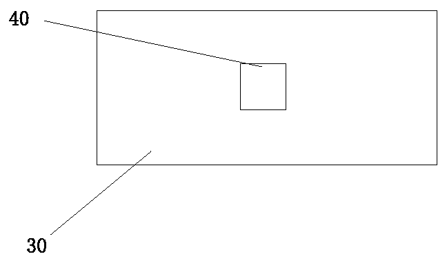
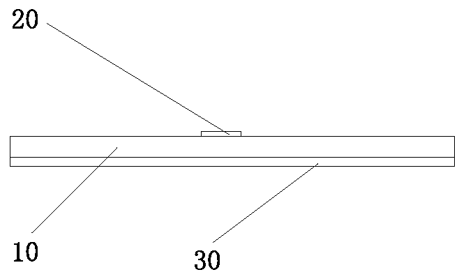
[0032] figure 1 A complete structural schematic diagram of a measuring system for measuring complex permittivity provided by the present invention, figure 2 and image 3 The top view and the front view of the CSRR microstrip resonant sensor are respectively the measurement part in the measurement system for measuring the complex permittivity provided by the present invention, such as Figure 1-Figure 3 As shown, the CSRR microstrip resonant sensor for measuring the complex permittivity provided by the present invention includes a dielectric substrate 10, a conductor signal line 20, a metal ground plate 30, a complementary split resonator ring 40 (hereinafter referred to as CSRR), and an SMA connecti...


PUM

PropertyMeasurementUnit
widthaaaaaaaaaa
thicknessaaaaaaaaaa
widthaaaaaaaaaa

Abstract

The invention relates to a CSRR (Complementary Split Ring Resonators) microstrip resonant sensor for measuring a complex dielectric constant and application thereof. The microstrip resonance sensor comprises a dielectric substrate, a conductor signal line, a metal grounding plate and a complementary split-ring resonator; the conductor signal line is printed right above the dielectric substrate, the metal grounding plate is integrally formed right below the dielectric substrate, and the complementary split-ring resonator is etched in the metal grounding plate. The CSRR microstrip resonance sensor for measuring the complex dielectric constant realizes measurement of the complex dielectric constant based on the CSRR, has the advantages of small size, light weight, low cost, high precision, nondestructive measurement, convenience in sample preparation and the like, and basically overcomes the defects of the traditional microwave measurement technology.

Description

technical field [0001] The invention relates to the technical field of microwave measurement, in particular to a CSRR microstrip resonant sensor for measuring complex dielectric constant and its application. Background technique [0002] At present, the measurement methods of dielectric constant using microwave technology mainly include free space method, transmission line method and resonance method. In the free space method, the Gaussian microwave beam focused antenna is placed on one or both sides of the substance to be measured, and the antenna terminal is connected to a vector network analyzer to measure the attenuation and phase constant to realize the measurement of the dielectric constant. This measurement method can be used in a wide range The complex dielectric constant can be measured in the frequency range, but the measurement accuracy is not high and the test equipment is expensive; the transmission line method usually needs to place the substance to be tested i...

Claims


Application Information

Patent Timeline
Patent Type & Authority Applications(China)
IPC IPC(8): G01R27/26
CPCG01R27/2623
Inventor 孙景芳赵颖涛王雅宁李然
Owner NORTH CHINA ELECTRIC POWER UNIV (BAODING)
Why Eureka
Try Eureka