

Heat insulation sleeve for battery and preparation method thereof
A heat insulation sleeve and battery technology, which is applied in the direction of battery box/jacket, battery box/cover material, secondary battery, etc., can solve the problems of limited heat insulation effect, volume energy density influence, increased weight, etc., and achieve excellent heat insulation Great effect on thermal performance and market application prospect
- Summary
- Abstract
- Description
- Claims
- Application Information
AI Technical Summary
Problems solved by technology
Method used
Image


Examples
preparation example Construction
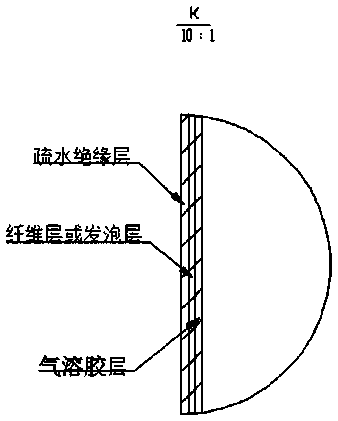
[0032] The preparation method of the battery heat insulating sleeve of the present application comprises the following steps:
[0033] (1) Airgel powder is mixed with water-based binder;
[0034] (2) soak the mixture of step (1) on the fiber layer or the foam layer and dry;
[0035] (3) Spray PTFE on the outside of the fiber layer for hydrophobic treatment.
Embodiment 1
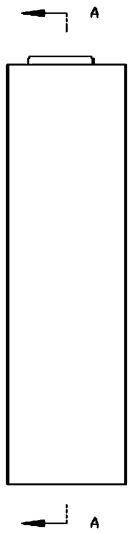
[0037] Such as figure 1 As shown, (1) SiO 2 Airgel powder and acrylic adhesive are mixed in a weight ratio of 6:4; (2) soak the mixture in step (1) on the polyester fiber with a thickness of 100 microns (um) and dry; (3) in the fiber layer Spraying on the outside: Polytetrafluoroethylene (PTFE) for hydrophobic treatment; (4) Make the three-layer heat insulation sleeve into a circular pipe with a flat diameter of 55 mm (mm); put the heat insulation sleeve on a phosphoric acid pipe with a diameter of 32 mm and a height of 140 mm. On the cylindrical battery of iron lithium, such as Figure 2-3 shown. When the fully charged single battery is short-circuited, test the temperature on the surface of the heat insulation cover, the maximum is 50 degrees Celsius (°C).
Embodiment 2
[0039] Such as figure 1 As shown, (1) SiO 2 Airgel powder and polyester adhesive are mixed in a weight ratio of 6:4; (2) soak the mixture in step (1) on the phenolic foam layer with a thickness of 100um and dry; (3) on the outside of the fiber layer Spray PTFE for hydrophobic treatment; (4) Make the three-layer heat insulation sleeve into a circular pipe with a flat diameter of 55mm; put the heat insulation sleeve on a lithium iron phosphate cylindrical battery with a diameter of 32mm and a height of 140mm, such as Figure 2-3 shown. When the fully charged single battery is short-circuited, the temperature on the surface of the heat insulation cover is tested, and the maximum is 53°C.
PUM
| Property | Measurement | Unit |
|---|---|---|
| Thickness | aaaaa | aaaaa |
| Granularity | aaaaa | aaaaa |
Abstract
Description
Claims
Application Information