
Long-stroke heavy-load high-precision multi-angle truss hybrid robot

A robot, high-precision technology, applied in the field of robotics, can solve the problems of high use and maintenance costs, high cost, integration complexity, etc., and achieve the effect of reducing production and operating costs, taking up less space, and reducing manufacturing costs.

Pending Publication Date: 2020-07-24
中创智造(苏州)智能装备科技有限公司
View PDF1 Cites 3 Cited by
  • Summary
  • Abstract
  • Description
  • Claims
  • Application Information

AI Technical Summary

Problems solved by technology

Although this method is feasible, it is expensive, and because the communication protocols of different brands of robots are different, the parts interfaces cannot be unified, so end users must stand in line with the robot brand, and the complexity of its integration also makes the use and maintenance costs of users later Rise, to a certain extent, reduces the willingness of users to use robots to complete automation upgrades
Although Chinese patent document 201310746524.0 mentions an XY Cartesian joint composed of three linear modules that are orthogonal to each other, it does not consider the integrability of parallel Cartesian joints in practical applications. The last three joints do not define the actual limited motion angle of the joints, which brings some inconvenience to the landing application. The robot design load in this document is 6KG, which is not suitable for heavy loads (50-100KG)

Method used


Image

  • Long-stroke heavy-load high-precision multi-angle truss hybrid robot
  • Long-stroke heavy-load high-precision multi-angle truss hybrid robot
  • Long-stroke heavy-load high-precision multi-angle truss hybrid robot

Examples


Embodiment Construction

[0017] The present invention will be described in detail below in conjunction with specific embodiments.

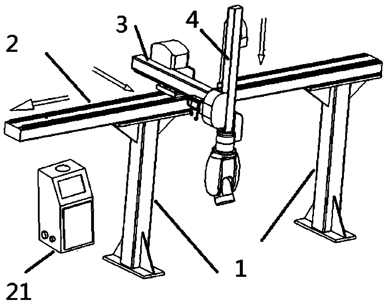
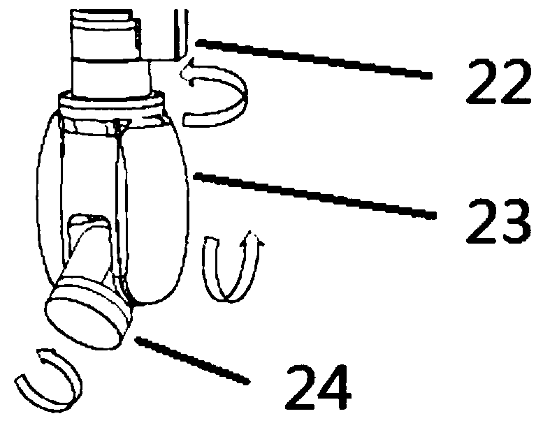
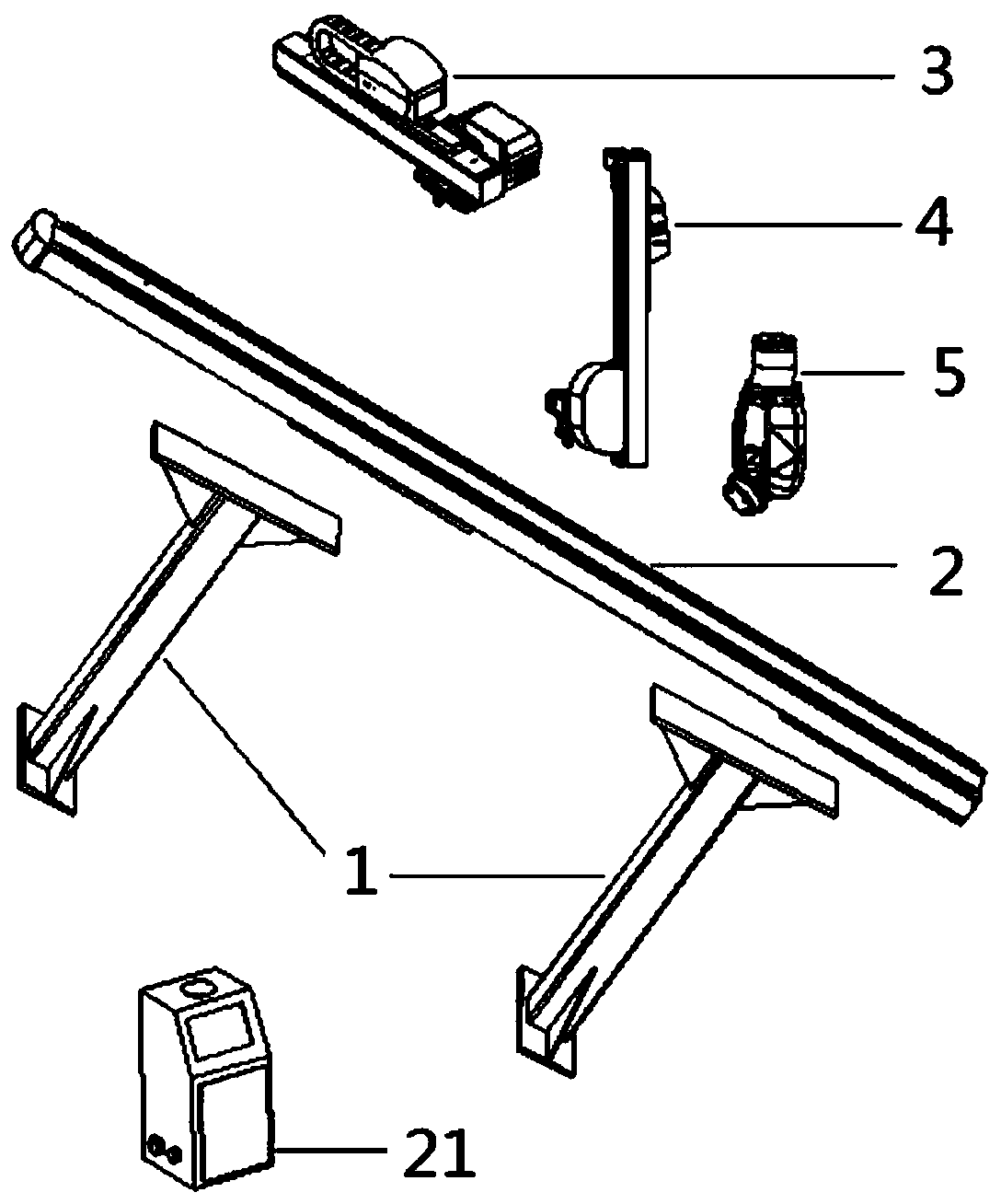
[0018] Such as Figure 1 to Figure 3 As shown, it is a long-stroke heavy-load high-precision multi-angle truss hybrid robot in accordance with the present invention, which includes a column (truss support) 1, an X axis (transverse entry and exit) 2, a Y axis (forward and backward) 3, and a Z axis. Axis (up and down) 4, rotary joint ABC axis (rotation and warping posture) 5, electric control unit 21.

[0019] The base of the truss hybrid robot adopts two columns 1 (a double truss support system that can be further expanded to four columns) to support the moving parts of its entire robot;

[0020] The X-axis 2 is the main beam on the column 1. The X-axis 2 can be lengthened or shortened according to actual needs and site space constraints. The common stroke range is within 0.5m to 10m, and can be further extended by splicing To more than 30 meters, the X-axis 2 completes ...


PUM


Abstract

The invention discloses a truss hybrid robot which comprises a truss base, three rectangular coordinate joints, namely an X shaft, a Y shaft and a Z shaft, and rotary joints A, B and C. The base is supported by two stand columns; the X shaft is a main cross beam and transversely erected on the stand columns; the Y shaft is perpendicularly transversely erected on the X shaft; the Z shaft is overlaid at the tail end of the Y shaft; the X shaft, the Y shaft and the Z shaft are all transmitted by a high-precision linear guide rail, a servo motor and a planetary gear, and three degrees of freedom of translation are achieved; the rotary joints A, B and C are arranged at the tail end of the Z shaft to realize three degrees of freedom of rotation; and each rotary joint is composed of a servo motor, a precision speed reducer, a shaft body and accessories. The truss hybrid robot overcomes the technical defects of a joint robot and a rectangular coordinate robot as a single robot, has the comprehensive parameters similar to or exceeding those of world mainstream robots, is high in reliability, good in universality and low in manufacturing cost, and is suitable for various occasions such as cross-station automatic transportation, welding, and machine tool feeding and discharging.

Description

technical field [0001] The invention relates to a robot, in particular to a long-stroke, heavy-load, high-precision, multi-angle truss hybrid robot, which is a six-degree-of-freedom hybrid robot based on XYZ rectangular coordinate joints and ABC rotary joints, and can be used in industrial and medical care scenarios. It belongs to the field of robotics. Background technique [0002] The existing mainstream general-purpose industrial robots are articulated robots and rectangular coordinate robots. Most articulated robots have more than three degrees of freedom in a series structure, but this structure cannot adapt to intelligent production lines with large-scale long-distance travel and heavy loads across workstations. Although the rectangular coordinate robot can meet the functions mentioned above, its end flexibility and positioning accuracy cannot meet the needs of smart factories. Therefore, in order to solve the contradictions in the above applications in reality, most...

Claims


Application Information

Patent Timeline
IPC IPC(8): B25J5/02B25J17/00B25J17/02B25J9/00
CPCB25J5/02B25J9/00B25J9/0009B25J17/00B25J17/02
Inventor 鲁精英
Owner 中创智造(苏州)智能装备科技有限公司
Learn More