Self-diagnosis gas density relay and using method thereof

A gas density, relay technology, applied in the field of electric power, can solve problems such as hazards, flashovers, and reduction of insulation strength on the surface of insulating parts

Pending Publication Date: 2020-07-24
SHANGHAI ROYE ELECTRICAL CO LTD
View PDF0 Cites 2 Cited by
  • Summary
  • Abstract
  • Description
  • Claims
  • Application Information

AI Technical Summary

Problems solved by technology

3) When the temperature drops, too much moisture may form condensation water, which will significantly reduce the insulation strength of the surface of the insulating part, or even flashover, causing serious damage
In addition, if the gas density on-line monitoring device or the remote density relay is calibrated or inspected, a lot of manpower and material resources are required

Method used


Image

  • Self-diagnosis gas density relay and using method thereof
  • Self-diagnosis gas density relay and using method thereof
  • Self-diagnosis gas density relay and using method thereof

Examples


Embodiment 1

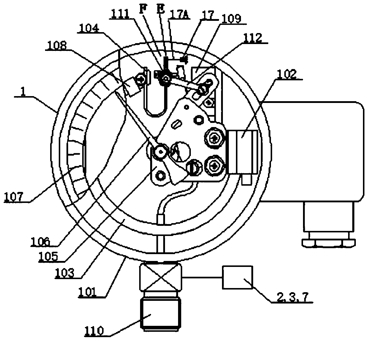
[0132] like figure 1 As shown, a self-diagnosing gas density relay or gas density monitoring device mainly includes: a gas density relay body 1, a gas density detection sensor (ie, a pressure sensor 2 and a temperature sensor 3), an intelligent control unit 7, and a diagnostic sensor 17 and Diagnostic sensor 19. Wherein, the pressure sensor 2, the temperature sensor 3 and the intelligent control unit 7 are arranged on the connector 110 for connecting electrical equipment. On the gas path, the pressure sensor 2 of the gas density detection sensor communicates with the gas density relay body 1 . The pressure sensor 2 , the temperature sensor 3 , the diagnostic sensor 17 and the diagnostic sensor 19 are respectively connected with the intelligent control unit 7 . The gas density relay or gas density monitoring device also includes a mutual self-calibration unit, and the data detected by the mutual self-calibration unit is compared through the intelligent control unit 7 to reali...

Embodiment 2

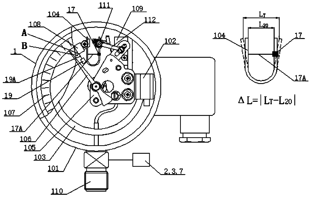
[0140] like figure 2 As shown, a self-diagnosing gas density relay or gas density monitoring device mainly includes: gas density relay body 1, gas density detection sensors (pressure sensor 2 and temperature sensor 3), intelligent control unit 7 and diagnostic sensor 17. Wherein, the pressure sensor 2, the temperature sensor 3 and the intelligent control unit 7 are arranged on the connector 110 for connecting electrical equipment. On the gas path, the pressure sensor 2 of the gas density detection sensor communicates with the gas density relay body 1 . The pressure sensor 2, the temperature sensor 3 and the diagnostic sensor 17 are respectively connected with the intelligent control unit 7. The gas density relay or gas density monitoring device also includes a mutual self-calibration unit, and the data detected by the mutual self-calibration unit is compared through the intelligent control unit 7 to realize maintenance-free; The detected data is compared to realize maintena...

Embodiment 3

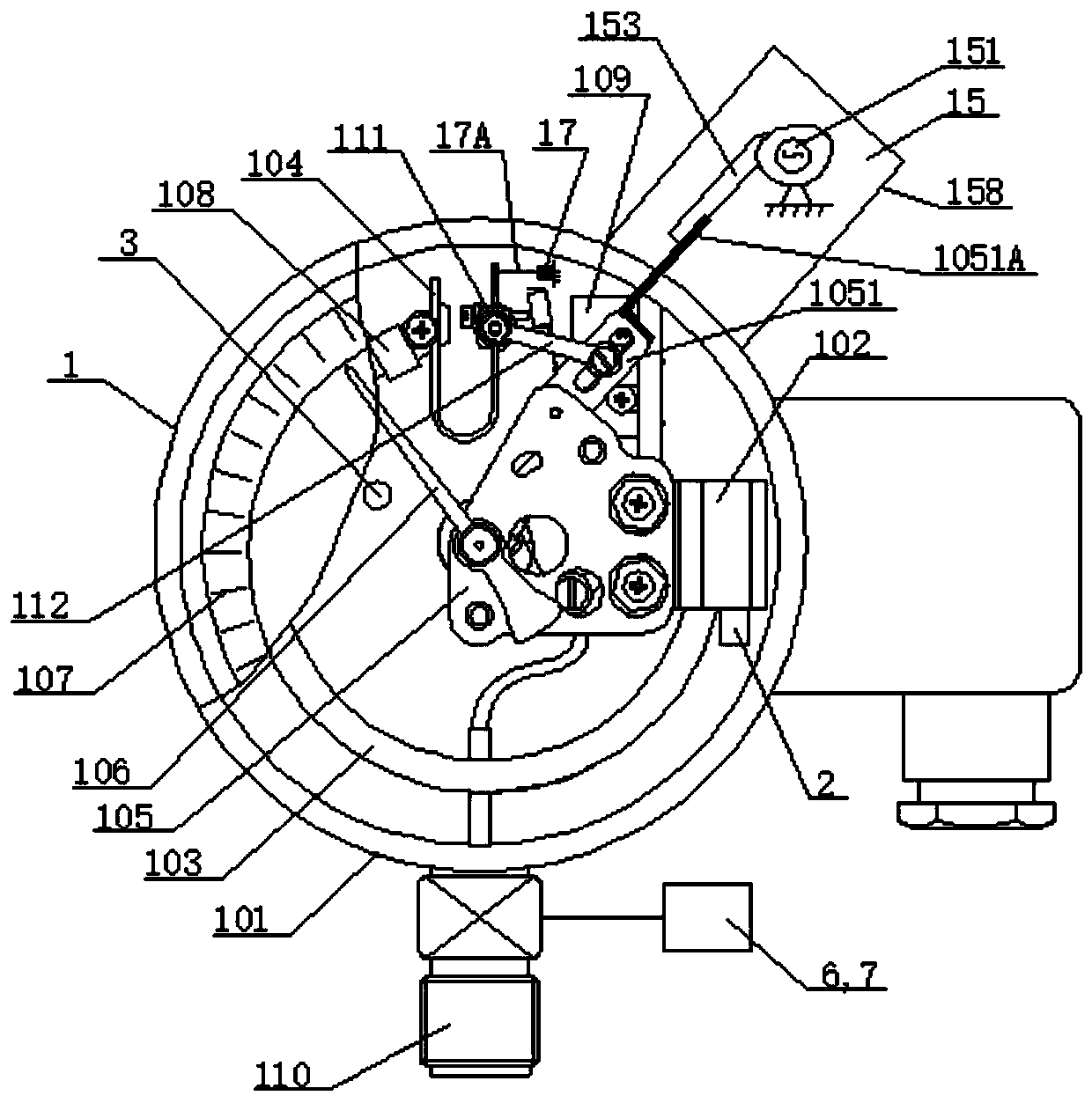
[0145] like image 3 As shown, the self-diagnosing gas density relay or gas density monitoring device of Embodiment 3 of the present invention includes: a gas density relay body 1, a pressure sensor 2, a temperature sensor 3, an actuating contact action mechanism 15, and an online verification contact signal sampling unit 6. Intelligent control unit 7 and diagnostic sensor 17. The online verification contact signal sampling unit 6 and the intelligent control unit 7 are arranged on the connector 110 for connecting electrical equipment. The driving contact action mechanism 15 is arranged outside the housing 101 .

[0146] Specifically, the gas density relay body 1 includes a housing 101, and a base 102, an end seat 108, a pressure detection element 103, a temperature compensation element 104, a number of signal generators 109, and a movement 105 arranged in the housing 101. , Pointer 106, Dial 107. Wherein, one end of the pressure detection element 103 is fixed on the base 10...


PUM


Abstract

The invention provides a self-diagnosis gas density relay and a using method thereof. The gas density relay comprises a gas density relay body, a gas density detection sensor, at least one diagnosis sensor and an intelligent control unit. The diagnosis sensor is configured to acquire a deformation quantity of a deformed part when pressure in the gas density relay body changes, or a temperature changes, or gas density changes, and/or a position or a displacement quantity of a displaced part; and the intelligent control unit is connected with the gas density detection sensor and the diagnosis sensor, receives data collected by the gas density detection sensor and/or the diagnosis sensor, and diagnoses a current working state of the gas density relay body. The gas density relay and the methodare used for monitoring the gas density of gas-insulated or arc-extinguished electrical equipment, meanwhile, online self-inspection of the gas density relay is completed, efficiency is improved, maintenance is not needed, operation and maintenance cost is greatly reduced, and safe operation of a power grid is guaranteed.

Description

technical field [0001] The invention relates to the field of electric power technology, in particular to a self-diagnosing gas density relay applied to high-voltage and medium-voltage electrical equipment and its application method. Background technique [0002] At present, SF6 (sulfur hexafluoride) electrical equipment has been widely used in the power sector and industrial and mining enterprises, which has promoted the rapid development of the power industry. In recent years, with the rapid economic development, the capacity of my country's power system has expanded rapidly, and the amount of SF6 electrical equipment has increased. The role of SF6 gas in high-voltage electrical equipment is arc extinguishing and insulation. If the density of SF6 gas in high-voltage electrical equipment decreases and the micro-water content exceeds the standard, it will seriously affect the safe operation of SF6 high-voltage electrical equipment: 1) The density of SF6 gas is reduced to a ce...

Claims


Application Information

Patent Timeline
Patent Type & Authority Applications(China)
IPC IPC(8): H01H35/26H01H35/32G01N9/00G01R31/327
CPCH01H35/26H01H35/32G01N9/00G01R31/327G01N2009/006G01N9/002H01H35/36H01H33/563H01H11/0062G01L7/041G01L7/045G01M3/3272
Inventor 金海勇夏铁新郭正操郝彩侠金海生
Owner SHANGHAI ROYE ELECTRICAL CO LTD
Why Eureka
Try Eureka