High-temperature pure air heater

An air heater, pure technology, applied in the field of hypersonic wind tunnel and aerodynamics, it can solve the problems of the outlet airflow temperature not meeting the requirements, the length-diameter ratio is difficult to obtain too large, the airflow residence time is short, etc. High temperature risk, high thermal storage temperature, effect of reducing operational risk

Active Publication Date: 2020-07-28
CHINA ACAD OF AEROSPACE AERODYNAMICS
View PDF23 Cites 9 Cited by
  • Summary
  • Abstract
  • Description
  • Claims
  • Application Information

AI Technical Summary

Problems solved by technology

[0007] However, in the existing electric heat storage heaters, the heat storage body is arranged in a single heat exchange channel, and the designed heater, the area of ​​the heat exchange channel is given according to the flow rate, and the length of the heater is determined; limited by the equipment site, the long If the diameter ratio is difficult to obtain too large, the heat exchange channel will be too short; the residence time of the air flow in the heat storage channel is short, and the temperature of the outlet air flow will not meet the requirements; if the preheating temperature of the heat storage body is simply increased , will cause the heater to overheat and cause safety problems;
[0008] In addition, the current vertically installed heater with a single channel, due to air convection, the upper temperature will continue to rise without restriction, and the temperature of the furnace top is very high; it will affect the safety of use
[0009] In the actual application of the heater, it is very difficu

Method used


Image

  • High-temperature pure air heater
  • High-temperature pure air heater
  • High-temperature pure air heater

Examples


Embodiment Construction

[0045] The present invention will be described in detail below in conjunction with the accompanying drawings. The same reference numerals represent the same components. The following embodiments are only descriptive, not restrictive, and cannot limit the protection scope of the present invention.

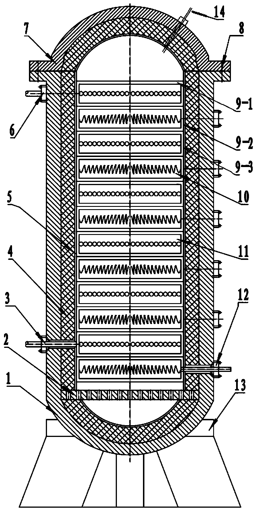
[0046] A high-temperature pure air heating device, which is a non-polluting way to obtain high-temperature airflow, compared with combustion and arc heating methods to obtain high-temperature gas with reaction products in the airflow, it can be used for experiments to obtain higher simulation accuracy . Such as figure 1 As shown, it includes pressure-resistant shell 1, furnace grate 2, air intake pipe 3, heat insulation layer 4, inner lining cylinder 5, air outlet pipe 6, upper cover plate 7, fastening bolts 8, corundum cover plate 9-1, insulation Seat 9-2, heat insulation support 9-3 (due to the reason of drawing scale, considering the clarity, figure 1 The middle corundum cover ...


PUM


Abstract

The invention provides a high-temperature pure air heater. The high-temperature pure air heater comprises a pressure-resistant shell (1), a grate (2), an air inflow pipe (3), a heat insulating layer (4), a lining barrel (5), an air outflow pipe (6), an upper cover plate (7), a fastening bolt (8), corundum parts (9-1, 9-2 and 9-3), electric heating assemblies (10), heat exchange assemblies (11), apower connector (12) and a support (13). The heat insulating layer (4) is mounted in the pressure-resistant shell (1), the electric heating assemblies (10) and the heat exchange assemblies (11) are combined up and down, and each electric heating assembly (11) is located on the lower portion of the corresponding heat exchange assembly (10). Heat exchange pipes of the heat exchange assemblies (11) are spirally arranged according to an involute and connected in series up and down, and connectors are inserted in a conical disc shape. The air inflow pipe (3) is arranged on the lower portion of thedevice, and the air outflow pipe (6) is arranged on the upper portion of the device. According to the air heater, the flow path of airflow is long, the heat exchange area is large, and the temperatureof the outlet airflow is stable. The heat exchange assemblies are vertically arranged, the internal heat insulating layer bears force uniformly, and the air heater is convenient to manufacture and machine and convenient to mount.

Description

technical field [0001] The invention relates to the field of aerodynamics, in particular to a hypersonic wind tunnel main airflow preheating device and a pure air heating device, belonging to the hypersonic wind tunnel technical field. Background technique [0002] Currently, there are two heating methods used in conventional hypersonic wind tunnels; instant heating and thermal storage. [0003] Instantaneous heaters are difficult to use in general laboratories due to the requirement of large electric power; general research test equipment, the number of operations is limited, the utilization rate is small, and conventional laboratories do not provide high-power power supply equipment, which limits this heater application. For example, in a hypersonic wind tunnel, the instantaneous electric heater needs a lot of electric power, and the power adjustment equipment. The wind tunnel of CARDC needs 8000KW electric power. For the small wind tunnel FD-03 hypersonic wind tunnel, on...

Claims


Application Information

Patent Timeline
IPC IPC(8): F24H3/04F24H9/18F24H9/00F24H9/20
CPCF24H3/0405F24H9/0052F24H9/1863F24H9/2071
Inventor 郭孝国倪招勇薛欣欣
Owner CHINA ACAD OF AEROSPACE AERODYNAMICS
Why Eureka
Try Eureka