
Motor insulated bearing chamber

A technology of insulated bearings and bearings, which is applied in the direction of casings/covers/supports, electrical components, electromechanical devices, etc., and can solve the problems that the rotor assembly cannot be effectively insulated, the service life of the device is reduced, and the bearing wears quickly, etc. Achieve the effect of improving the transmission effect of the shaft, facilitating heat dissipation and improving performance

Inactive Publication Date: 2020-07-28
DANYANG LANSI INFORMATION TECH CO LTD
View PDF3 Cites 0 Cited by
  • Summary
  • Abstract
  • Description
  • Claims
  • Application Information

AI Technical Summary

Problems solved by technology

[0004] However, the motor with insulation performance in the rotor bearing chamber provided in the above technical solution still has many disadvantages in actual use, such as the rotor assembly cannot be effectively insulated, and it is not easy to dissipate heat, which makes the bearing wear faster and reduces the Device life

Method used


Image

  • Motor insulated bearing chamber
  • Motor insulated bearing chamber
  • Motor insulated bearing chamber

Examples


Embodiment 1

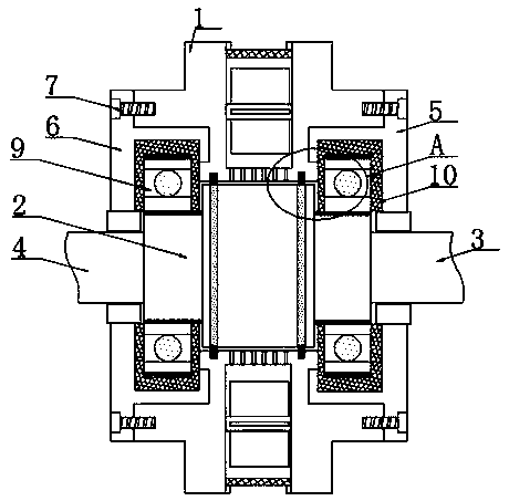
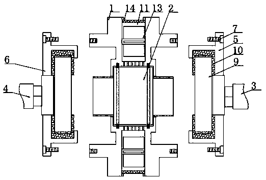
[0028] according to Figure 1-6 The insulating bearing chamber of a motor shown includes a housing 1, a shaft coupling 2 is provided inside the housing 1, and a driving shaft 3 is provided at one end of the coupling 2, and the coupling 2 is far away from the driving shaft 3 is provided with a driven shaft 4, the housing 1 is provided with a front cover 5 on a side close to the driving shaft 3, and a rear cover 6 is provided on a side of the housing 1 close to the driven shaft 4, so Both sides of the housing 1 are provided with first threaded holes, and the surfaces of the front cover 5 and the rear cover 6 are provided with second threaded holes, and the front cover 5 and the rear cover 6 pass through the housing 1. The screw 7 is fixedly connected, and the front cover 5 and the rear cover 6 are fixedly connected with an annular clamp 8, and the axis of the annular clamp 8 is provided with a bearing 9, and the bearing 9 and the annular clamp 8 An insulating layer 10 is provid...

Embodiment 2

[0031] according to Figure 4 As shown in the motor insulation bearing chamber, the outer side of the housing 1 is provided with an annular groove 11, and the bottom of the annular groove 11 is provided with a number of evenly distributed exhaust holes 12, and the exhaust holes 12 are connected with the housing 1 through the inside, the annular groove 11 is provided with a number of evenly distributed cooling fans 13, the honeycomb structure of the insulating layer 10 facilitates the heat dissipation of the bearing 9, the heat enters the annular groove 11 from the exhaust hole 12 and passes through the cooling fan 13 discharge, which is conducive to the long-term work of the motor;

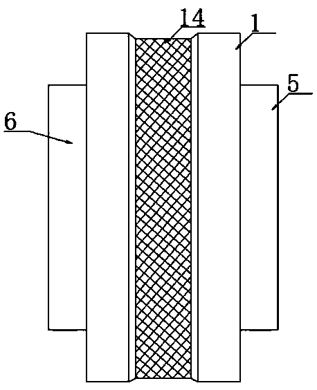
[0032] Further, the top of the annular groove 11 is provided with a dust-proof net 14, the dust-proof net 14 is made of metal material, the dust-proof net 14 is arranged in a strip shape, and the dust-proof net 14 is fixed around the annular At the top of the groove 11, the dust-proof net 14 can ...


PUM


Abstract

The invention discloses a motor insulated bearing chamber, and specifically relates to the field of motors. The motor insulated bearing chamber comprises a shell, wherein the shell is internally provided with a coupling, a driving shaft is arranged at one end of the coupling, a driven shaft is arranged at the end, which is away from the driving shaft, of the coupling, a front cover plate is arranged on the side, which is close to the driving shaft, of the shell, a rear cover plate is arranged on the side, which is close to the driven shaft, of the shell, first threaded holes are formed in thetwo sides of the shell, and second threaded holes are formed in the surfaces of the front cover plate and the rear cover plate. According to the invention, the coupling is arranged, the driving shaftand the driven shaft are inserted into two ends of the coupling, the rotating shaft is enabled to be insulated, the outer sides of the two ends of the coupling are both provided with bearings, the outer side of each bearing is provided with an insulating layer, the shell can be isolated from the bearings, the shell is enabled to be isolated from the bearings, and the insulating effect of the bearing chamber is improved. In addition, the front cover plate and the rear cover plate are fixedly connected with the shell through screws, the installation is convenient, parts are convenient to maintain and replace, the insulating layers are arranged in a honeycomb shape, heat dissipation is facilitated, and the motor performance can be improved.

Description

technical field [0001] The invention relates to the field of motors, and more specifically, the invention relates to an insulating bearing chamber for a motor. Background technique [0002] With the development of electronic application technology, frequency converter and its control technology are more and more widely used in motors, and it is inevitable that motors work on high-frequency power sources. High-order harmonics are difficult to eliminate, resulting in shaft current, which is very harmful to the bearing. When the motor has shaft current, the current will form a loop between the stator and rotor of the motor through the bearing. When the shaft current When passing through the bearing, the internal grease film will be broken down by the axial current, and over time, it will cause electrical corrosion to the grooves and rolling elements of the bearing, which will cause the bearing to run worse and worse, and the grease will dry up and heat up and burn the bearing, ...

Claims


Application Information

Patent Timeline
IPC IPC(8): H02K5/16H02K5/10H02K9/04H02K5/20H02K7/08
CPCH02K5/16H02K5/10H02K9/04H02K5/20H02K7/08
Inventor 杨慧
Owner DANYANG LANSI INFORMATION TECH CO LTD
Learn More