
Hard alloy cutter with internal spiral cooling liquid hole and production equipment thereof

A technology of cemented carbide and production equipment, which is applied to other manufacturing equipment/tools, turbines, engine components, etc., and can solve problems such as damage to workpieces, complex structures, and easy cracks

Inactive Publication Date: 2020-07-31
江西耀升钨业股份有限公司
View PDF4 Cites 1 Cited by
  • Summary
  • Abstract
  • Description
  • Claims
  • Application Information

AI Technical Summary

Problems solved by technology

Drills, end mills, taps, reamers, etc. produced from this bar have the advantages of good cooling effect, high chip removal efficiency, good surface finish, and long tool life. Traditional processing cutting tools are used as industrial processing tools. The more commonly used workpieces are widely used in processing lathes. Since lathe processing generally processes metal workpieces, metal workpieces are prone to overheating during processing, which will not only cause damage to the processed workpieces, but also the processed products. There are also certain flaws. At present, the equipment for producing inner spiral cooling hole cemented carbide rods relies on the traditional mold cavity and transmission handle, punch base, rigid helical punch, and die to form a combined mold. The structure is complex and easy. Cracks occur, therefore, we propose a cemented carbide tool with an inner spiral coolant hole and its production equipment in order to solve the above-mentioned problems

Method used


Image

  • Hard alloy cutter with internal spiral cooling liquid hole and production equipment thereof
  • Hard alloy cutter with internal spiral cooling liquid hole and production equipment thereof
  • Hard alloy cutter with internal spiral cooling liquid hole and production equipment thereof

Examples


Embodiment Construction

[0030] In order to make the object, technical solution and advantages of the present invention clearer, the present invention will be further described in detail below in conjunction with the accompanying drawings and embodiments. It should be understood that the specific embodiments described here are only used to explain the present invention, not to limit the present invention.

[0031] In the description of the present invention, it should be noted that the terms "center", "upper", "lower", "left", "right", "front", "rear", "vertical", "horizontal", The orientation or positional relationship indicated by "inner", "outer", etc. is based on the orientation or positional relationship shown in the drawings, and is only for the convenience of describing the present invention and simplifying the description, rather than indicating or implying that the referred device or element must have Certain orientations, constructed and operative in certain orientations, therefore are not t...


PUM


Abstract

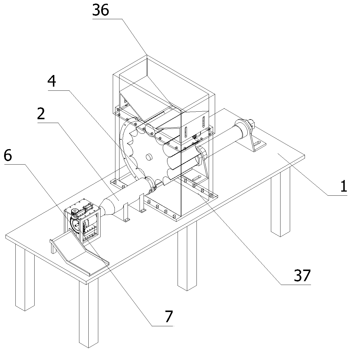
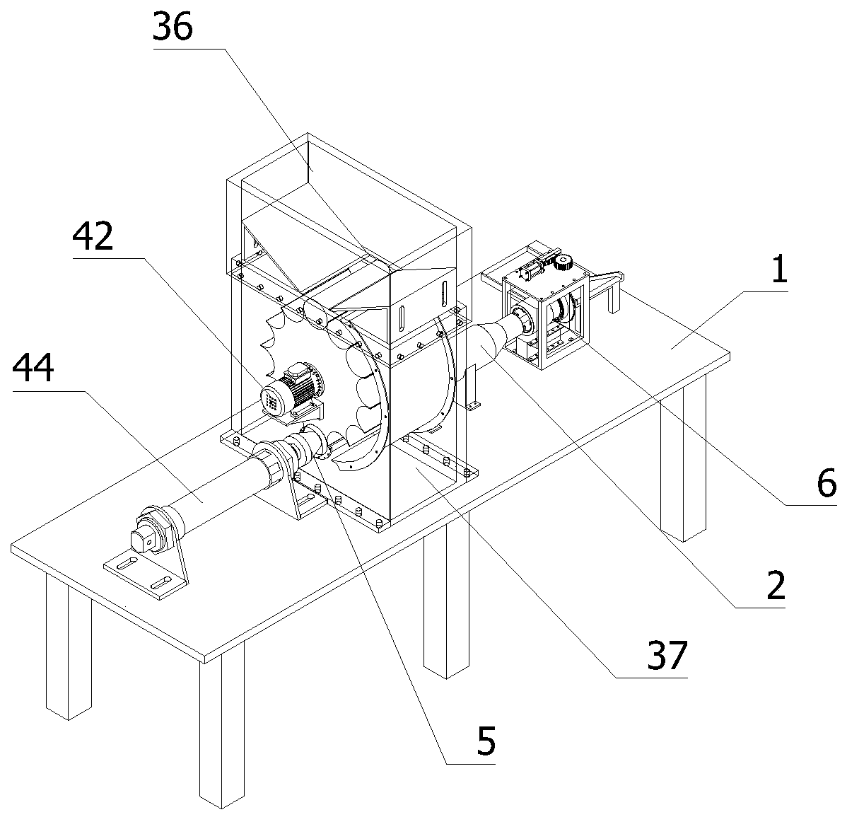
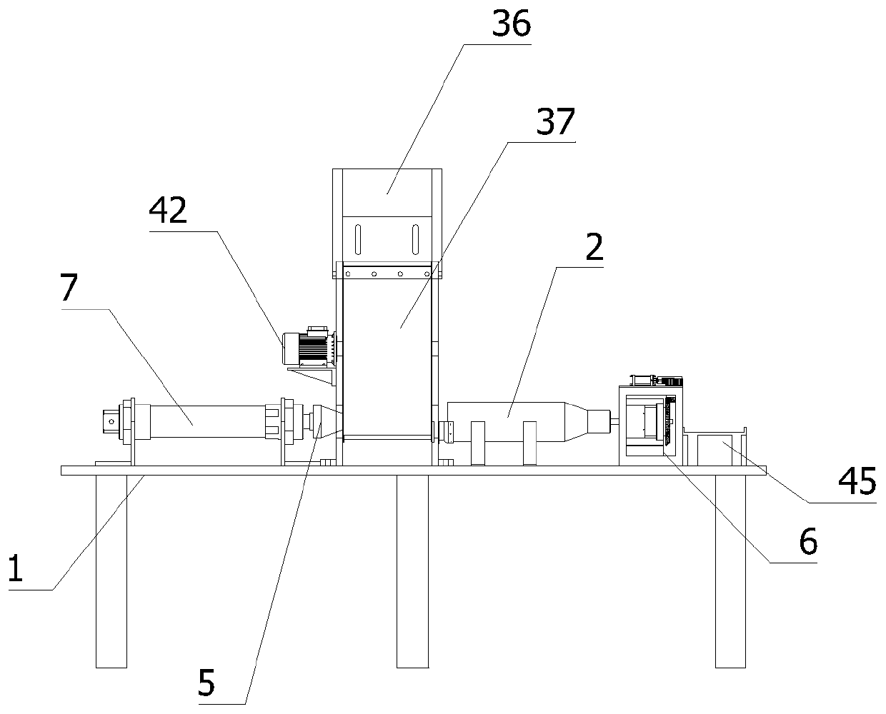
The invention relates to the technical field of hard alloy cutters, in particular to a hard alloy cutter with an internal spiral cooling liquid hole and production equipment thereof. The production equipment comprises a machining table and further comprises a material supplying mechanism, an extrusion mold mechanism and a cooling discharging mechanism; the extrusion mold mechanism comprises a heating feeding sleeve and a forming mold; the heating feeding sleeve comprises a feeding inlet and a discharging outlet, and the forming mold is installed in the position, located at the discharging outlet, of the heating feeding sleeve; the material supplying mechanism comprises a material supplying bin, the material supplying bin is provided with a material guide opening, and the interior of the material supplying bin is provided with an extrusion head; the cooling discharging mechanism comprises a rotary cooling assembly and a discharging table; and the rotary cooling assembly comprises a cooling bin, the cooling bin is provided with a round through hole penetrating through two surfaces, and the interior of the round through hole is provided with cooling spray heads. According to the technical scheme, through the extrusion forming mold, the size stability of a hard alloy round bar product with the internal spiral hole can be improved, the appearance is attractive, the percent of pass is high, in addition, cooling can be automatically conducted, and the production quality is improved.

Description

technical field [0001] The invention relates to the technical field of cemented carbide cutting tools, in particular to a cemented carbide cutting tool with an inner spiral cooling liquid hole and production equipment thereof. Background technique [0002] The cemented carbide rod with internal spiral cooling hole is a representative product of ultra-fine cemented carbide high-tech. Drills, end mills, taps, reamers, etc. produced from this bar have the advantages of good cooling effect, high chip removal efficiency, good surface finish, and long tool life. Traditional processing cutting tools are used as industrial processing tools. The more commonly used workpieces are widely used in processing lathes. Since lathe processing generally processes metal workpieces, metal workpieces are prone to overheating during processing, which will not only cause damage to the processed workpieces, but also the processed products. There are also certain flaws. At present, the equipment fo...

Claims


Application Information

Patent Timeline
IPC IPC(8): B22F5/00B22F3/00B22F3/20B22F3/24
CPCB22F5/00B22F3/004B22F3/20B22F3/24B22F3/005B22F3/003B22F2005/001B22F2003/208
Inventor 郭建锋刘小平郭名亮郭家亮李永顺黄绍泽蔡运花
Owner 江西耀升钨业股份有限公司
Learn More