Thin-wall stainless steel pipe cutting machine capable of preventing scrap iron from splashing

A technology of stainless steel pipe and pipe cutting machine, applied in the direction of pipe shearing device, shearing device, manufacturing tools, etc., can solve the problems of sparks and iron filings damage, cutting blade operator damage, etc., to reduce labor, facilitate collection, The effect of avoiding damage

Pending Publication Date: 2020-07-31
张家港市越泰精密机械有限公司
View PDF0 Cites 6 Cited by
  • Summary
  • Abstract
  • Description
  • Claims
  • Application Information

AI Technical Summary

Problems solved by technology

[0004] The purpose of the present invention is to solve the problems existing in the prior art that when the workers are operating, the splashed sparks and iron filings will cause damage to the relevant workers, causing the workers to have the possibility of being scratched and the staff holding the When the stainless steel pipe is inadvertently loaded, the cutting piece will cause damage to the relevant operators, and a thin-walled stainless steel pipe cutting machine with the ability to prevent iron filings from splashing is proposed

Method used


Image

  • Thin-wall stainless steel pipe cutting machine capable of preventing scrap iron from splashing
  • Thin-wall stainless steel pipe cutting machine capable of preventing scrap iron from splashing
  • Thin-wall stainless steel pipe cutting machine capable of preventing scrap iron from splashing

Examples


Embodiment Construction

[0030] The following will clearly and completely describe the technical solutions in the embodiments of the present invention with reference to the accompanying drawings in the embodiments of the present invention. Obviously, the described embodiments are only some, not all, embodiments of the present invention. Based on the embodiments of the present invention, all other embodiments obtained by persons of ordinary skill in the art without making creative efforts belong to the protection scope of the present invention.

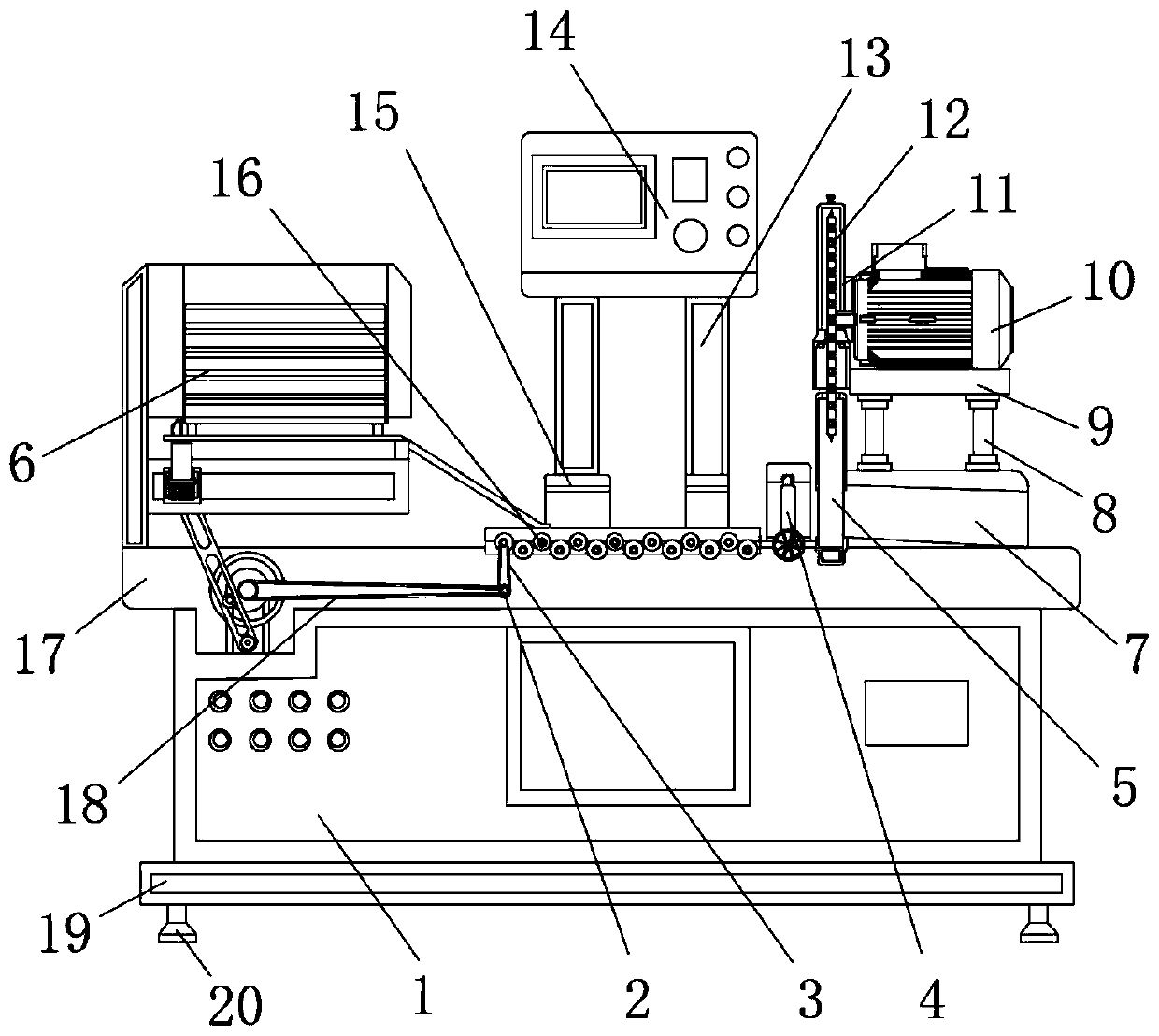
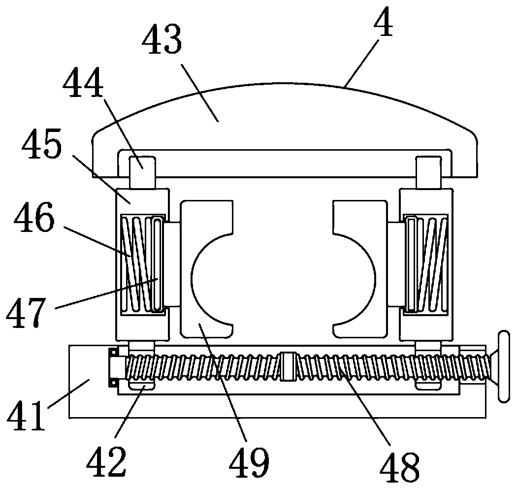
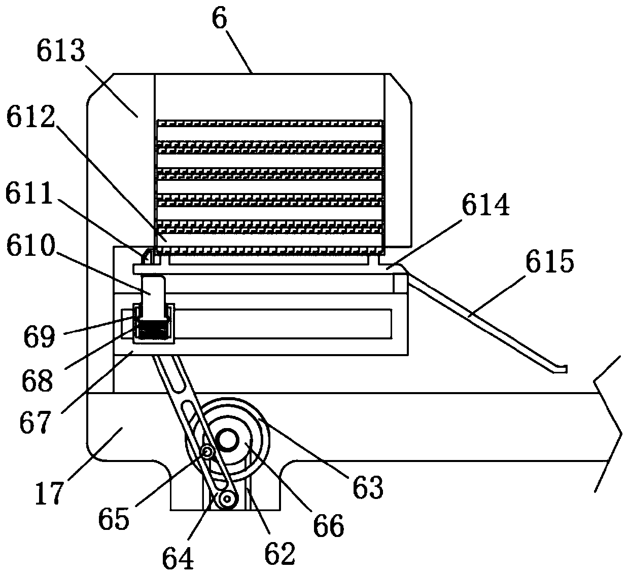
[0031] Please refer to Figure 1-9 , the present invention provides a technical solution: a thin-walled stainless steel pipe cutting machine capable of preventing iron filings from splashing, comprising a pipe cutting machine body 1, the bottom end of the pipe cutting machine body 1 is fixedly connected to a base 19, and the base 19 The bottom end is fixedly connected with a leg 20, the top of the pipe cutting machine body 1 is fixedly connected with a support...


PUM


Abstract

The invention discloses a thin-wall stainless steel pipe cutting machine capable of preventing scrap iron from splashing. The thin-wall stainless steel pipe cutting machine comprises a pipe cutting machine body, wherein the bottom end of the pipe cutting machine body is fixedly connected with a base, and the bottom end of the base is fixedly connected with supporting legs; the top end of the pipecutting machine body is fixedly connected with a supporting table, and a transmission mechanism is fixedly arranged on the left side of the top end of the supporting table; and a first roller is arranged on the transmission mechanism, and the surface of the first roller is connected with a fixed rotating wheel through a second connecting belt. According to the thin-wall stainless steel pipe cutting machine, a protection mechanism is arranged, a first protection plate and a second protection plate are arranged on the protection mechanism, the first protection plate and the second protection plate are matched with each other so as to wrap a cutting piece, and the scrap iron and sparks can be effectively prevented from splashing during cutting; and meanwhile, the scrap iron can be collected and stored through a closed space formed by combining the first protection plate and the second protection plate, and a push block pushes the stainless steel pipe body to move in the moving process, sothat the stainless steel pipe body slides to the surface of a sliding cylinder along a sliding plate.

Description

technical field [0001] The invention relates to the technical field of pipe cutting machines, in particular to a thin-walled stainless steel pipe cutting machine capable of preventing iron filings from splashing. Background technique [0002] Stainless steel pipe cutting machine is a kind of metal pipe cutting machine. As the name implies, the stainless steel pipe cutting machine is a machine specially designed for cutting stainless steel pipes. The automatic stainless steel pipe cutting machine can quickly cut stainless steel pipes and adjust the diameter of the cutting product at will. In addition, it can also be humanized. Set the cutting size, cutting speed, cutting quantity and stop without material, etc. The pipe cutting machine is connected to the vise to clamp the material through the hydraulic cylinder, and the material is conveyed forward through PLC or CNC system control, and the worm gear and worm in the gearbox are driven by the motor rotation. The gear thus dri...

Claims


Application Information

Patent Timeline
Patent Type & Authority Applications(China)
IPC IPC(8): B23D21/00B23Q11/08B23Q7/00B23Q7/10B23Q7/05B23Q3/06
CPCB23D21/00B23Q3/064B23Q7/00B23Q7/055B23Q7/10B23Q11/08
Inventor 阳江斌吴士化
Owner 张家港市越泰精密机械有限公司
Why Eureka
Try Eureka