A sizing device based on the application of glass fiber yarn
A glass fiber yarn and sizing tube technology, which is applied in the processing of textile material cleaning device, textile material processing, liquid/gas/vapor yarn/filament processing, etc., can solve the problems of easy impact, affecting yarn quality, inconvenience, etc. , to achieve the effect of improving quality, reducing area and reducing production cost
- Summary
- Abstract
- Description
- Claims
- Application Information
AI Technical Summary
Problems solved by technology
Method used
Image
Examples
Embodiment 1
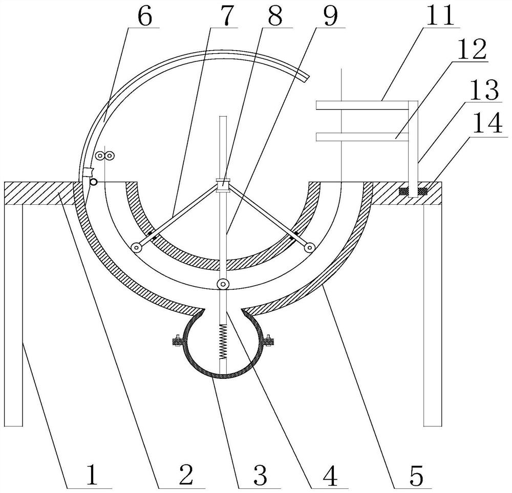
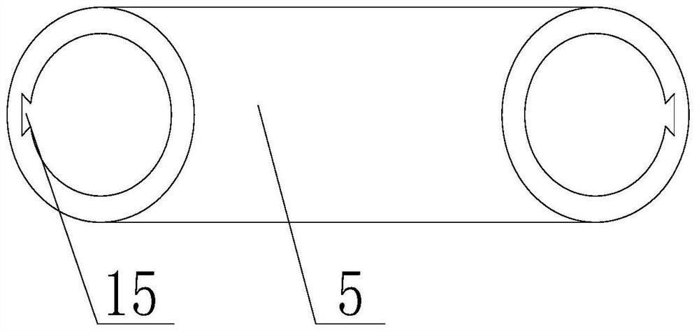
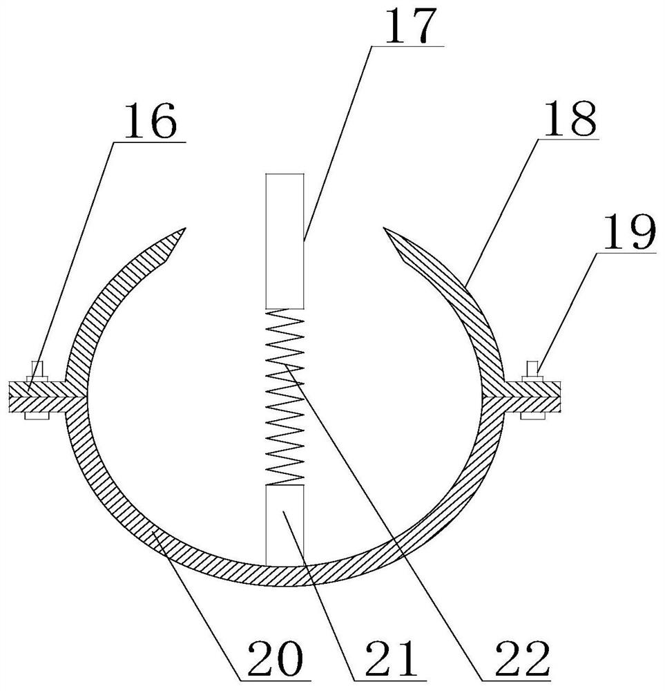
[0039] Such as Figure 1 to Figure 7 As shown, a sizing device based on glass fiber yarn application in the present invention includes a support platform 2, a support foot 1 is provided at the bottom of the support platform 2, and a U-shaped sizing pipe 5 is provided at the top of the support platform 2 , the settling chamber 3 of the bottom spherical structure of the sizing pipe 5, the settling chamber 3 communicates with the sizing pipe 5, the settling chamber 3 is provided with a telescopic plate 4, and the telescopic plate 4 includes a first connecting plate 17, a second An elastic member 22 and a second connecting plate 21, one end of the second connecting plate 21 is connected to the inner bottom of the sedimentation chamber 3, the other end is connected to the first elastic member 22, one end of the first connecting plate 17 is connected to the first elastic 22, the other end extends into the sizing pipe 5, the inner wall of the sizing pipe 5 is provided with a guide gr...
Embodiment 2
[0041] On the basis of Embodiment 1, the sizing pipe 5 is also provided with a vertical rod 9, the vertical rod 9 is vertically inserted into the sizing pipe 5, and the end of the vertical rod 9 located in the sizing pipe 5 is provided with a second A roller, the top of the first connecting plate 17 is in contact with the first roller.
Embodiment 3
[0043] On the basis of Embodiment 2, the vertical bar 9 is also provided with a movable block 8, the movable block 8 is sleeved on the vertical bar 9, and the movable block 8 can move along the axial direction of the vertical bar 9, the Both sides of the movable block 8 are provided with a slanting rod 7, one end of the slanting rod 7 is hinged with the movable block 8, and the other end extends into the sizing pipe 5, the end of the slanting rod 7 located in the sizing pipe 5 is also provided with a second Two rollers.
PUM
 Abstract
Description
Claims
Application Information
 - R&D
- Intellectual Property
- Life Sciences
- Materials
- Tech Scout
- Unparalleled Data Quality
- Higher Quality Content
- 60% Fewer Hallucinations
Browse by: Latest US Patents, China's latest patents, Technical Efficacy Thesaurus, Application Domain, Technology Topic, Popular Technical Reports.
© 2025 PatSnap. All rights reserved.Legal|Privacy policy|Modern Slavery Act Transparency Statement|Sitemap|About US| Contact US: help@patsnap.com


