
Flexible baseline dynamic prediction method based on fiber grating sensor and wing mode

A fiber grating and sensor technology, applied in the field of navigation, can solve the problems of time asynchrony, poor rapidity, unsuitable for dynamic measurement, etc.

Active Publication Date: 2020-07-31
BEIHANG UNIV
View PDF5 Cites 1 Cited by
  • Summary
  • Abstract
  • Description
  • Claims
  • Application Information

AI Technical Summary

Problems solved by technology

As a technology for distributed master nodes to assist in aligning sub-node poses, transfer alignment is a key technology for distributed POS. However, transfer alignment technology still needs further research in terms of flexible lever arm conditions and real-time dynamic alignment.
On the one hand, from the perspective of the flexible baseline measurement method, the existing method based on the FBG sensor to obtain the displacement through fitting has a relatively large amount of calculation and poor rapidity, which is not suitable for dynamic measurement; on the other hand, based on the FBG sensor The calculation of the conversion from the measured strain to the baseline takes time, but in the actual flight process, the transfer alignment between the main node and the sub-node and the strain measurement of the current wing by the sensor are carried out simultaneously, so the baseline converted by the sensor at the current measurement time cannot be calculated. Real-time is used to transfer the alignment process at the current moment, resulting in time out-of-sync problems

Method used


Image

  • Flexible baseline dynamic prediction method based on fiber grating sensor and wing mode
  • Flexible baseline dynamic prediction method based on fiber grating sensor and wing mode
  • Flexible baseline dynamic prediction method based on fiber grating sensor and wing mode

Examples


Embodiment Construction

[0097] The present invention will be further described below in conjunction with the accompanying drawings and specific embodiments.

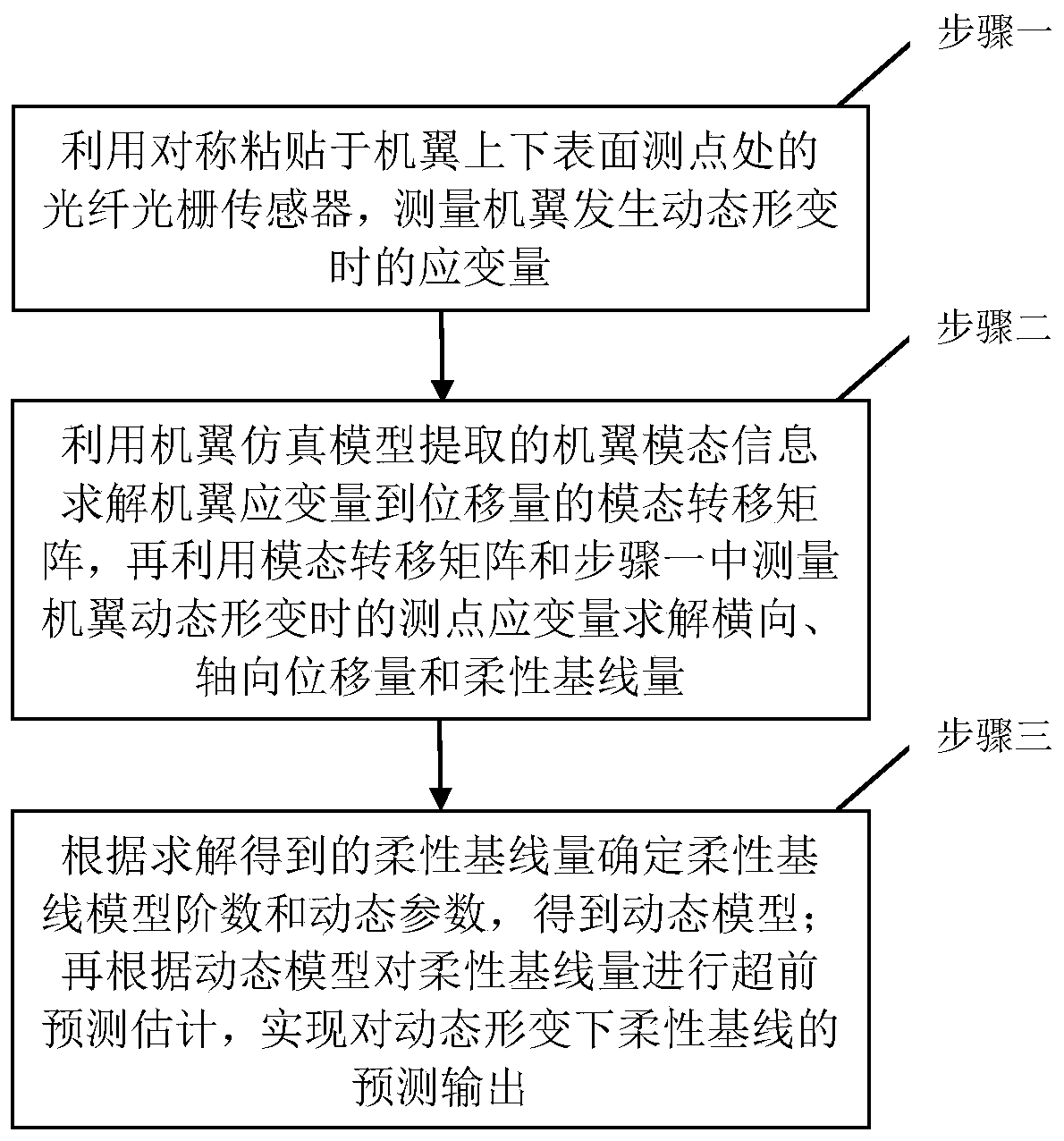
[0098] Such as image 3 As shown, a flexible baseline dynamic prediction method based on fiber grating sensor and wing modality, including the following technical steps:

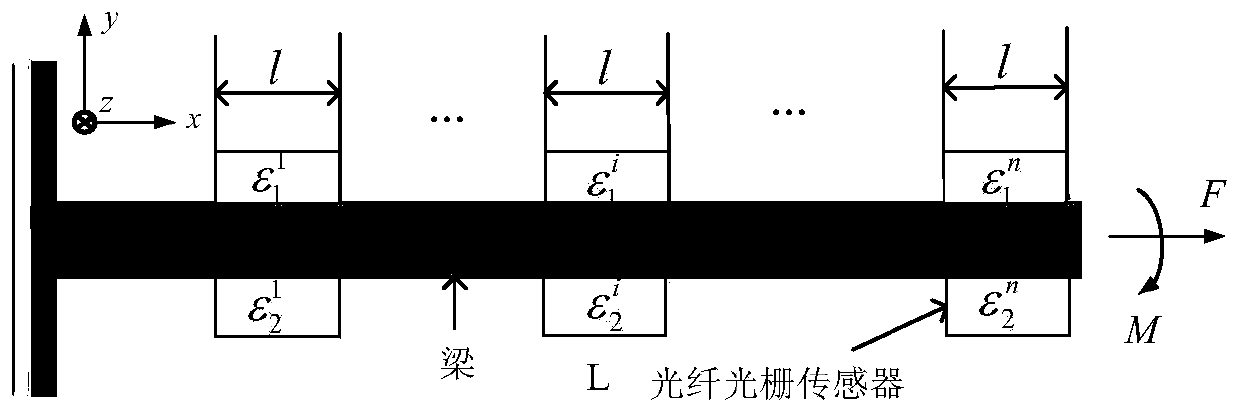
[0099] 1. According to the optical fiber grating sensor pasted symmetrically on the upper and lower surface of the wing at the measuring point, measure the strain of the measuring point when the wing is dynamically deformed.

[0100] In actual operation, the steps are as follows:

[0101] (1) Keep the wing in a straight state and stand still for 5 minutes, and obtain the wavelength at each measuring point of the fiber grating as the initial wavelength reference;

[0102] (2) According to the basic principle of measuring strain with the aforementioned fiber grating sensor, the time-varying wavelength at the measuring point of the fiber grating at the measuring point on the u...


PUM


Abstract

The invention discloses a flexible baseline dynamic prediction method based on a fiber grating sensor and a wing mode. According to the invention, the method comprises: employing a modal superpositionprinciple based on structural strain response to calculate structural displacement and a base line variable between child nodes, and then predicting a base line quantity change condition at a futuremoment by a base line dynamic model established based on flexible base line real-time data; employing the modal method to reduce the calculation amount and employing dynamic modeling to predict the flexible baseline in advance so as to solve the problem of real-time transfer alignment time delay caused by time consumption of resolving from the actual measurement dependent variable to the base linevariable, thereby facilitating the realization of high-precision pose real-time transfer alignment of child nodes. The method can be used for remarkably improving the real-time performance of transfer alignment and making up for the defects of previous baseline solution and estimation method research.

Description

technical field [0001] The invention belongs to the field of navigation, and relates to a flexible baseline dynamic prediction method based on an optical fiber grating sensor and a wing mode. Background technique [0002] In recent years, the airborne distributed POS (Position and Orientation System) has been widely used in the field of aviation, national defense and military, especially in the field of multi-task imaging load high-precision earth observation, because of its characteristics of multi-node measurement and high pose accuracy. application. As a technology for distributed master nodes to assist in aligning sub-node poses, transfer alignment is a key technology for distributed POS. However, transfer alignment technology still needs further research in terms of flexible lever arm conditions and real-time dynamic alignment. On the one hand, from the perspective of the flexible baseline measurement method, the existing method based on the FBG sensor to obtain the di...

Claims


Application Information

Patent Timeline
IPC IPC(8): G06F30/20G06F17/16G06F17/12
CPCG06F17/16G06F17/12Y02T90/00
Inventor 朱庄生谭浩徐起飞贾悦
Owner BEIHANG UNIV
Learn More