Eureka AIR delivers breakthrough ideas for toughest innovation challenges, trusted by R&D personnel around the world.

Variable-frequency constant-pressure water supply assembly

A technology of variable frequency constant pressure and components, which is applied to water supply devices, water conservation, water supply main pipelines, etc., can solve problems such as increased pressure, excessive pressure difference inside and outside the pipeline, and cracking of the outer wall of the pipeline, so as to improve efficiency, increase strength, Effect of raising efficiency of cleaning

Active Publication Date: 2020-08-04
SHANGHAI BANGPU INDAL GROUP
View PDF6 Cites 0 Cited by
  • Summary
  • Abstract
  • Description
  • Claims
  • Application Information

AI Technical Summary

Problems solved by technology

[0003] The existing patent numbers CN104060649B and CN209873945U both propose variable frequency constant pressure water supply components. When supplying water, the pipeline is usually extended directly into the water. However, during the movement of the ship, as the position changes, the pressure on the water surface will increase and decrease. It acts directly on the pipeline, and the water flow is flowing relative to the pipeline, which will increase the pressure effect. After the ship has been running for a long time, the pipeline is likely to be broken due to the excessive pressure difference between the inside and outside of the pipeline, etc.

Method used


Image

  • Variable-frequency constant-pressure water supply assembly
  • Variable-frequency constant-pressure water supply assembly
  • Variable-frequency constant-pressure water supply assembly

Examples


Embodiment 1

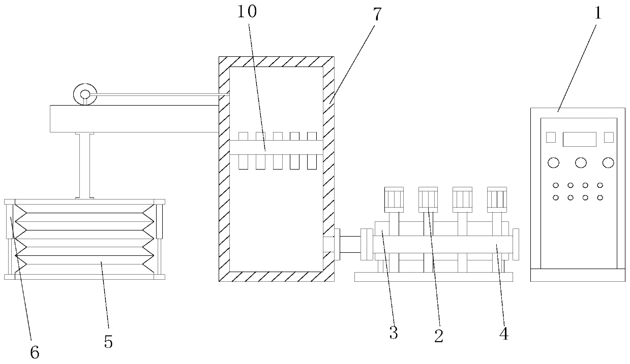
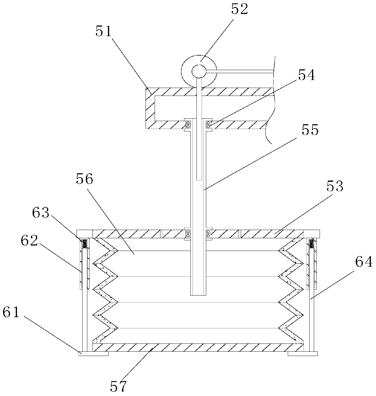
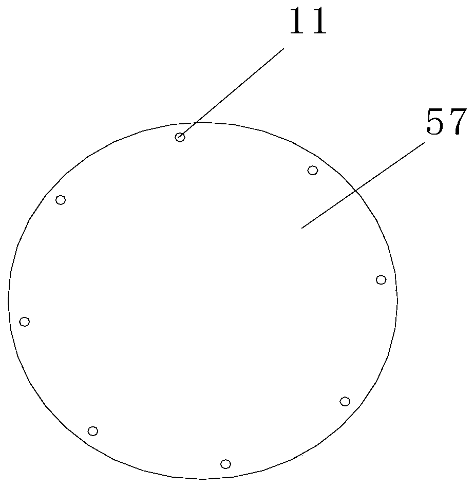
[0042] Example 1: Please refer to Figure 1-4 , a variable frequency constant pressure water supply assembly, including an electric control cabinet 1, a water pump group 2, a pressure tank 3, a water supply pipe 4, a water collecting mechanism 5, a telescopic mechanism 6 and a water storage tank 7, and the interior of the electric control cabinet 1 is fixedly installed with electric Control system and ABB inverter, electric control cabinet 1 is electrically connected with water pump group 2, water pump group 2, air pressure tank 3 and water supply pipe 4 are all arranged on the left side of electric control cabinet 1, and the water inlet end of water supply pipe 4 is connected to the storage The water tank 7 is fixedly connected and communicated, the interior of the water storage tank 7 is fixedly installed with a filtering mechanism 10, and the filtering mechanism 10 adopts a reverse osmosis membrane filtration mechanism, and the reverse osmosis membrane filtration mechanism i...

Embodiment 2

[0046] Example 2: Please refer to Figure 5-6 , on the basis of the first embodiment, the undulations of the outer wall of the bellows 56 are sleeved with the rubber sleeve 13, the rubber sleeve 13 is in the shape of a circular ring and the side close to the bellows 56 is in a hollow state, and the rubber sleeve 13 shrinks in the bellows 56 When the bellows 56 is stretched, it is also in a contracted state and is attached to the outer wall of the bellows 56. The inner wall of the bellows 56 is provided with a through hole 14 at the position corresponding to the rubber sleeve 13. After the bellows 56 is stretched, the rubber sleeve 13 will also stretch. The through hole 14 is used to accommodate part of the water, and then when the water collecting mechanism 5 is stopped, the rubber sleeve 13 also shrinks during the shrinkage process of the bellows 56, and the stored water is squeezed out. Water is used to flush the inner wall of the bellows 56. Through the setting of the rubbe...

Embodiment 3

[0049] Example 3: Please refer to Figure 7-8 , On the basis of the second embodiment, the bottom surface of the connecting pipe 55 is fixedly connected with the water purification tank 17, the interior of the clean water tank 17 is hollow and communicated with the connecting pipe 55, and the bottom surface of the scraper 16 is provided with five water inlet grooves A18, the scraper Inside 16, a water inlet tank B19 is opened above the water inlet tank A18, the water inlet tank B19 is connected with the five water inlet tanks A18, the top surface of the water inlet tank B19 is provided with a water outlet hole 20, and the inner wall of the water outlet hole 20 is fixedly connected with a water supply pipe 21, One end of the water supply pipe 21 away from the water outlet hole 20 is fixedly connected and communicated with the clean water tank 17, and the filter screen 22 is fixedly installed on the inner wall of the water inlet tank A18. And between the scraper 16, the process ...


PUM


Abstract

The invention relates to the technical field of water supply, and discloses a variable-frequency constant-pressure water supply assembly. The variable-frequency constant-pressure water supply assemblycomprises an electric control cabinet, a water pump set, an air pressure tank, a water supply pipe, a water collection mechanism, a telescopic mechanism and a water storage tank; an electric controlsystem and an ABB frequency converter are fixedly installed inside the electric control cabinet; the water pump set, the air pressure tank and the water supply pipe are arranged on the left side of the electric control cabinet; the water inlet end of the water supply pipe is fixedly connected and communicated with the water storage tank; a filtering mechanism is fixedly installed inside the waterstorage tank, and the filtering mechanism adopts a reverse permeable membrane filtering mechanism; the water collection mechanism is fixedly arranged on the left side of the water storage tank; the telescopic mechanism is fixedly arranged on the water collection mechanism; through the arrangement of a corrugated pipe, a bottom plate can sink through the weight change after water enters the bottomplate, so that a water collecting space is enlarged, the deformation range can be freely changed according to the strength of the external water pressure, the effect of automatically balancing internal pressure and external pressure is achieved, and compared with arrangement of an existing water collection mechanism, the variable-frequency constant-pressure water supply assembly has the advantageof avoiding damage to the water collection mechanism caused by excessive increase of external water pressure.

Description

technical field [0001] The invention relates to the technical field of water supply, in particular to a variable frequency constant pressure water supply assembly. Background technique [0002] The variable frequency constant pressure water supply equipment is a new type of energy-saving water supply equipment. The existing variable frequency constant pressure water supply equipment is also widely used on medium and large ships. [0003] The existing patent numbers CN104060649B and CN209873945U both propose a variable frequency constant pressure water supply assembly, which usually extends the pipeline directly into the water when supplying water. Directly acting on the pipeline, and the flow of water relative to the pipeline will increase the effect of the pressure. After the ship runs for a long time, the pipeline is prone to breakage due to the excessive pressure difference between the inside and outside of the pipeline. Therefore, a variable frequency constant pressure...

Claims


Application Information

Patent Timeline
Patent Type & Authority Applications(China)
IPC IPC(8): E03B7/07E03B11/06
CPCE03B7/07E03B7/074E03B7/075E03B11/06Y02A20/00
Inventor 刘庆顺
Owner SHANGHAI BANGPU INDAL GROUP
Why Eureka
Eureka Blog
Learn More