Quick response hydraulic control valve of high-pressure common rail fuel injector

A hydraulic control valve, fast-response technology, applied in machine/engine, fuel injection device, engine components, etc., can solve the problems of limited practical effect, inability to control the delay of opening and closing of the injector at the same time, etc.

Pending Publication Date: 2020-08-04
无锡格林鲍尔科技有限公司
View PDF0 Cites 0 Cited by
  • Summary
  • Abstract
  • Description
  • Claims
  • Application Information

AI Technical Summary

Problems solved by technology

[0003] In order to reduce the duration, it is necessary to reduce the opening or closing delay of the injector assembly during the injection process. The existing diesel injectors cannot simultaneously control the opening and closing delay of the injector. That is to say, the current control valve Solution, in order to reduce the duration, if the parameters of the flow difference between the inlet and outlet holes are matched, there will be a hyperbolic effect on the opening delay and closing delay, and the final actual effect is very limited

Method used


Image

  • Quick response hydraulic control valve of high-pressure common rail fuel injector
  • Quick response hydraulic control valve of high-pressure common rail fuel injector
  • Quick response hydraulic control valve of high-pressure common rail fuel injector

Examples


Embodiment 1

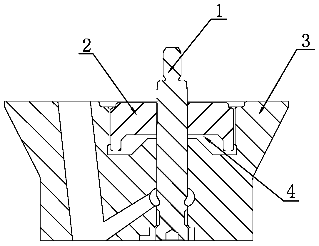
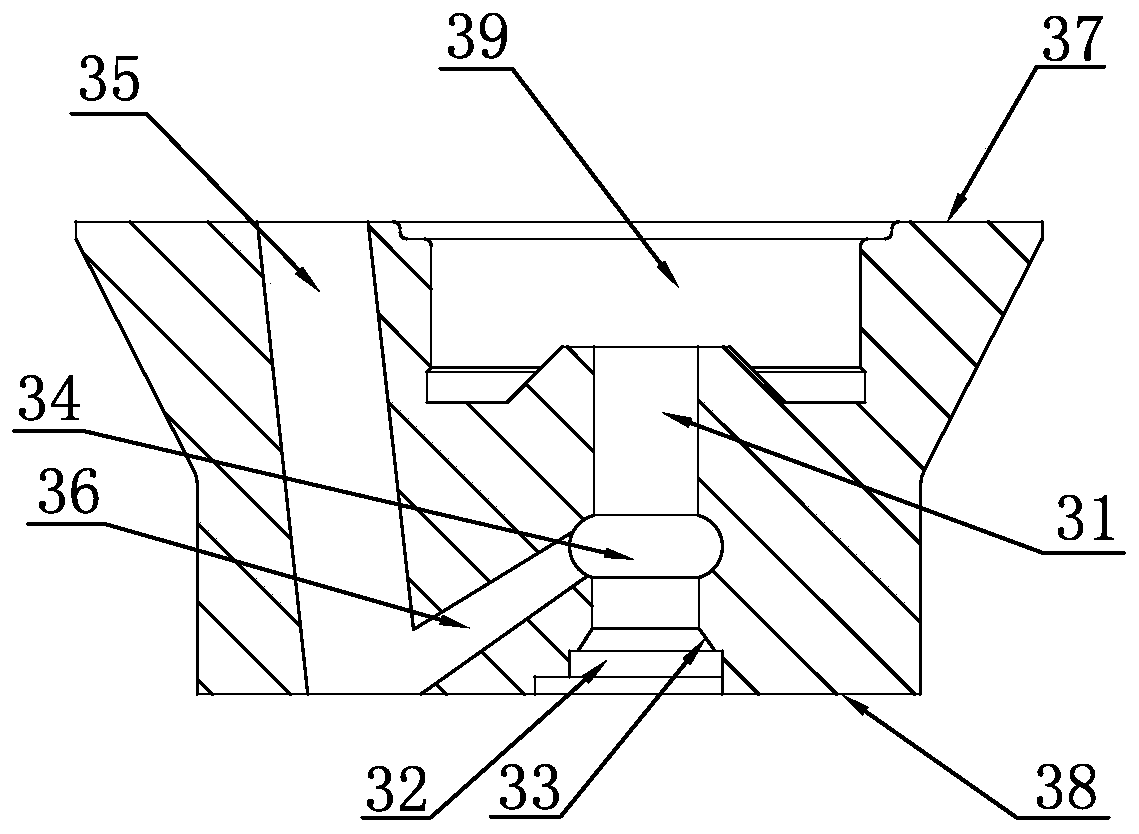
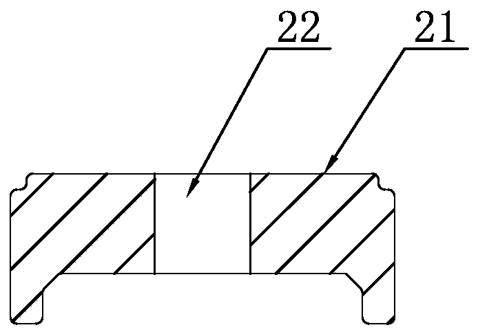
[0020] A quick-response hydraulic control valve for a high-pressure common rail fuel injector, characterized in that it includes a valve core post 1, an armature plate 2 and a control valve seat 3; the valve core post includes a spring limit section 11, a guide post 12, Intermediate sealing section 13, concave space 14, oil storage groove 15, end surface groove 16, guide rod lower end surface 17, oil storage groove tapered surface 18, axial limit post 19, intermediate sealing section 13, concave space 14 and The oil storage grooves 15 are all arranged on the guide column 12, the axial limit column 19 is arranged at the lower end of the guide column 12, the spring limit section 11 is arranged at the upper end of the guide column 12, and the end surface groove 16 is arranged on the lower end surface of the guide rod At the center of 17, the conical surface 18 of the oil storage groove is arranged on the lower side of the oil storage groove 15, and the guide column 12 of the valve...

Embodiment 2

[0024] Embodiment 2: The difference from Embodiment 1 is that the diameter of the axial limit post 19 is 0.2-2 mm larger than the diameter of the valve core guide hole 31 .


PUM


Abstract

The invention discloses a quick response control valve of a high-pressure common rail fuel injector. The quick response control valve comprises a valve spool column, an armature disc and a control valve seat; the valve spool column is provided with a specific structure, the control valve seat is provided with a valve spool guide hole, a comprehensive containing cavity, an oil inlet conical surface, an oil passing annular groove, a valve seat oil inlet channel, an inclined oil way channel and a valve spool cavity form a quick response control oil way, and in a free state, the cover top surfaceof the armature disc is lower than the upper end surface of the valve seat to form an opening and closing top gap. The control valve with the structure is matched with the corresponding throttle valveto directly control an oil nozzle, so that the response speed is increased, and the duration can be shortened.

Description

Technical field: [0001] The invention relates to a fast-response diesel engine common rail fuel injector, in particular to a hydraulic control valve therein. Background technique: [0002] During the working process of the common rail injector assembly of the diesel engine, it needs to experience a certain delay time from the injector receiving the injection start pulse signal to the injector realizing the injection. This delay time is called the opening delay time; and From the injector receiving the injection closing pulse signal to the injection closing, a certain delay time also needs to end. This delay time is called the closing delay time; the shorter the opening delay and closing delay time, the better the response of the injector. Faster, and the faster the injector responds, the more conducive to the working stability of the injector, which is conducive to increasing the engine speed that the injector assembly is adapted to, and is also conducive to improving the po...

Claims


Application Information

Patent Timeline
IPC IPC(8): F02M61/16F02M47/02F02M63/00
CPCF02M47/027F02M61/16F02M63/0056
Inventor 刘义亭吴小勇庄福如沙有胜鞠得雨王进钱音瑶赵波李明
Owner 无锡格林鲍尔科技有限公司
Why Eureka
Try Eureka