Electric timing belt wheel

A synchronous pulley and electric technology, applied in the direction of electric components, belts/chains/gears, electromechanical devices, etc., can solve the problems of uneven appearance of pulleys, low processing efficiency, complicated procedures, etc., to promote automation and intelligence, Improve the tightness of the connection and keep it clean

Pending Publication Date: 2020-08-04
上海亘本科技有限公司
View PDF0 Cites 2 Cited by
  • Summary
  • Abstract
  • Description
  • Claims
  • Application Information

AI Technical Summary

Problems solved by technology

However, it is found in use that the driving device of the existing synchronous pulley is mostly arranged outside the synchronous pulley, which takes up a certain space and causes unnecessary troubles for the overall planning of the equipment or the overall planning of the production line; In the case of synchronous pulleys, if one is broken, all the wheels need to be removed, which is inconvenient for maintenance
In addition, in the synchronous belt drive, in order to prevent deviation due to the non-parallel axis of the pulley, it is usually necessary to install retaining rings on both sides of the pulley, and the retaining rings can be fastened to the side of the pulley by screws. Making corresponding via holes and threaded holes on the retaining ring and pulley and assembling them is complex and costly; if riveting, spot welding and other methods are used to connect the pulley and retaining ring, riveting or welding equipment is required at this time. Low processing efficiency, poor reliability, uneven appearance of the pulley

Method used


Image

  • Electric timing belt wheel
  • Electric timing belt wheel
  • Electric timing belt wheel

Examples


Embodiment Construction

[0017] The present invention will be described in further detail below in conjunction with the accompanying drawings.

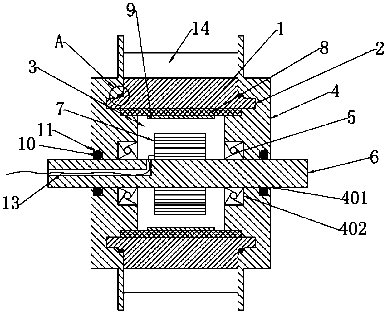
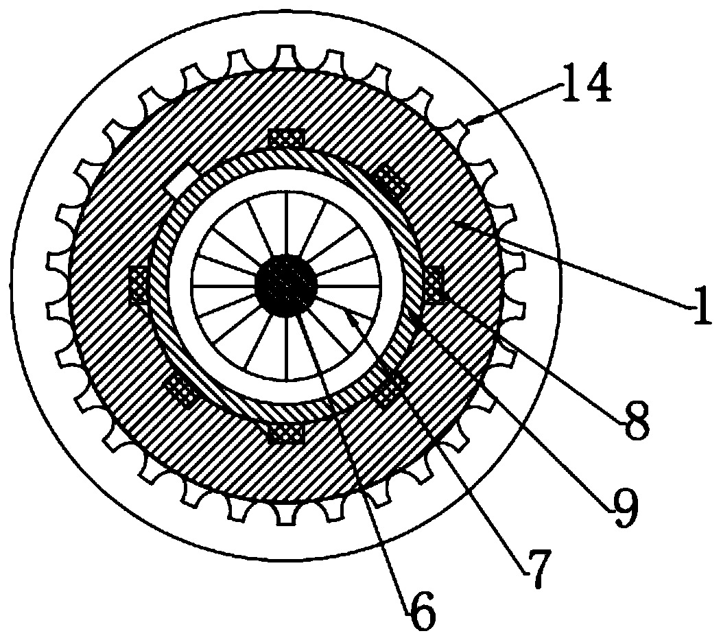
[0018] An electric synchronous pulley, comprising a pulley body 1 with protrusions 2 at both ends, the axis of the pulley body 1 and the protrusions 2 at both ends is provided with the pulley body 1 and the protrusions 2 at both ends The central round hole 3 of the said protrusion 2 is connected with an end cover 4, the axis line of the end cover 4 is provided with a shaft hole 401 communicating with the central round hole 3, and the end cover 4 is close to the pulley body 1 A bearing installation hole 402 is provided on one side coaxially with the shaft hole 401, and a bearing 5 is installed in the bearing installation hole 402, and a fixed shaft 6 is coaxially installed on the two end covers 4 through the bearing 5, and the fixed shaft 6 is located in the center A stator coil 7 is installed inside the round hole 3 , and a rotor yoke 8 is provided inside the...


PUM


Abstract

The invention belongs to the technical field of mechanical equipment, and particularly relates to an electric timing belt wheel. The electric timing belt wheel comprises a belt wheel body provided with protrusions. A central circular hole penetrating through the belt wheel body and the protrusions is formed in the axis of the belt wheel body and the protrusions. End covers are arranged on the protrusions, and shaft holes communicated with the central circular hole are formed in the axis lines of the end covers. A bearing mounting hole is coaxially formed in one side, close to the belt wheel body, of the end cover with the shaft hole. Bearings are installed in the bearing mounting holes, and a stationary shaft is coaxially arranged on the two end covers through the bearings. The part in thecentral circular hole of the stationary shaft is provided with stator coils. Rotor magnet yokes are arranged on the inner side of the belt wheel body around the stator coils, and permanent magnets are arranged on the inner sides of the rotor magnet yokes around the stator coils. According to the electric timing belt wheel, a driving device and a motor are arranged in the belt wheel, so that spaceoccupation is reduced, convenience is provided for the design of equipment or production line and maintenance, and the automation and intelligence of production equipment are promoted.

Description

technical field [0001] The invention belongs to the technical field of mechanical equipment, in particular to an electric synchronous pulley. Background technique [0002] The synchronous pulley drive is composed of a closed ring-shaped belt with equidistant teeth on the inner peripheral surface and the corresponding pulley. When moving, the teeth of the belt mesh with the tooth grooves of the pulley to transmit motion and power. It is a kind of meshing transmission, so it has various characteristics of gear transmission, chain transmission and flat belt transmission. Widely used in automobiles, textiles, printing and packaging equipment, sewing equipment, office equipment, laser engraving equipment, tobacco, financial equipment, stage lighting, communication food machinery, medical machinery, steel machinery, petrochemical, instrumentation, various precision machine tools It is also widely used in various automation and intelligent industrial production. However, it is fo...

Claims


Application Information

Patent Timeline
Patent Type & Authority Applications(China)
IPC IPC(8): F16H55/17F16H55/12F16H55/46F16H57/023F16H57/029H02K5/04H02K1/27H02K1/18
CPCF16H55/12F16H55/171F16H55/46F16H57/023F16H57/029F16H2055/176H02K1/187H02K1/2786H02K5/04
Inventor 郎小强
Owner 上海亘本科技有限公司
Why Eureka
Try Eureka