

Optical measurement system
An optical measurement system and optical unit technology, applied in optical radiation measurement, measurement device, color/spectral characteristic measurement, etc., can solve the problems of increased system complexity and reduced grating light energy utilization, and achieve reduced complexity and easy Engineering realization, the effect of reducing the number of parts
- Summary
- Abstract
- Description
- Claims
- Application Information
AI Technical Summary
Problems solved by technology
Method used
Image

Examples
Embodiment 1
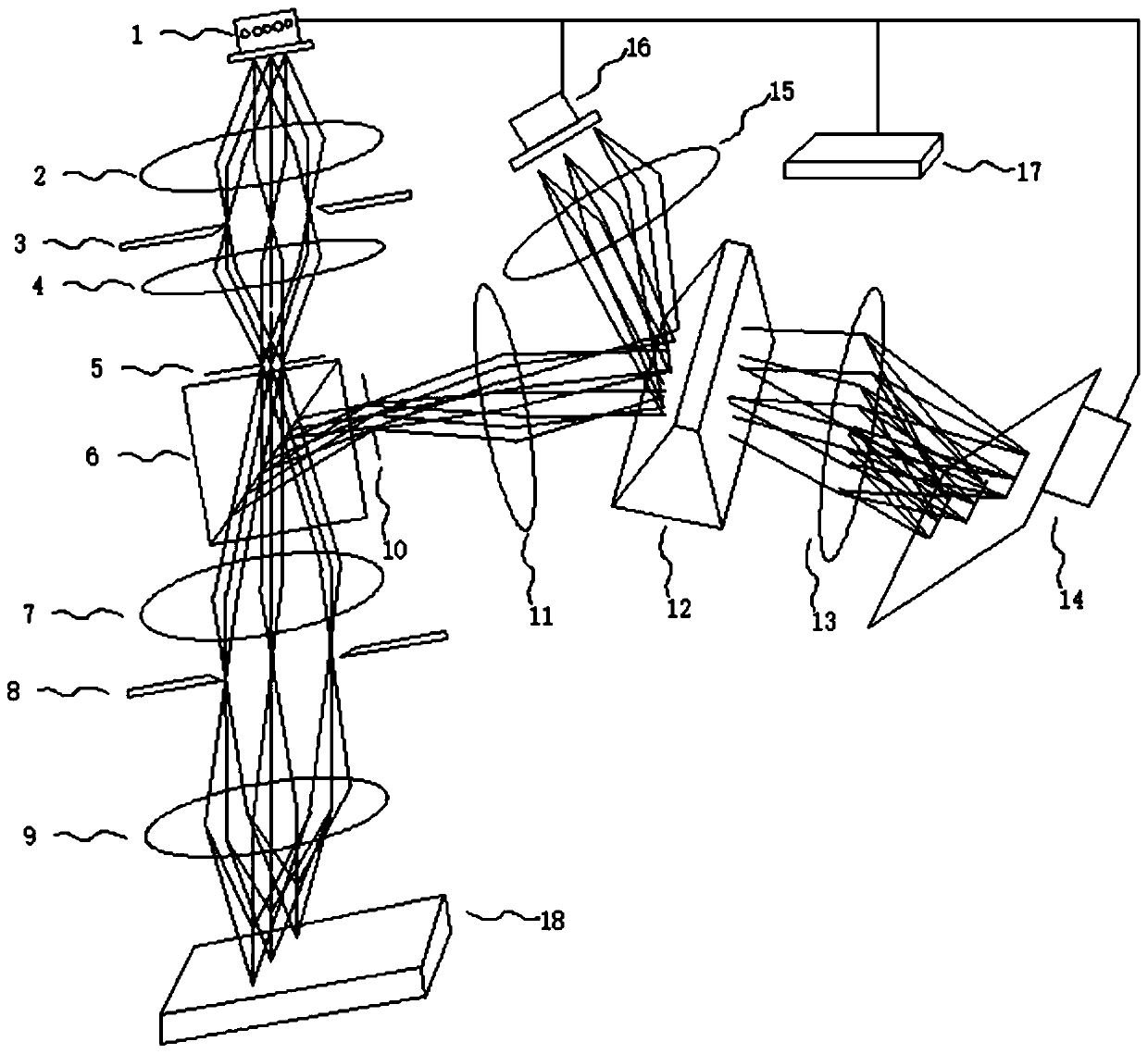
[0031] This embodiment provides a Figure 1-2Optical measurement system shown. The optical measurement system includes a light source (the light source in this embodiment is a linear light source 1), a first optical unit, a second optical unit, a dispersion element (the dispersion prism 12 is used as a preferred solution in this embodiment for illustration), a linear array detector Device 16, area array detector 14, main control system 17. After the light beam emitted by the continuous-spectrum linear light source 1 is transmitted through the first optical unit, the emitted light beam is split by the second optical unit. The light emitting side of the first optical unit can also be provided with a first slit 5, the light beam emitted by the light source is transmitted through the first optical unit and then irradiated on the first slit 5, and the light emitting surface of the light source and the first slit 5 form an object image conjugate relationship, the light beam exits ...
Embodiment 2
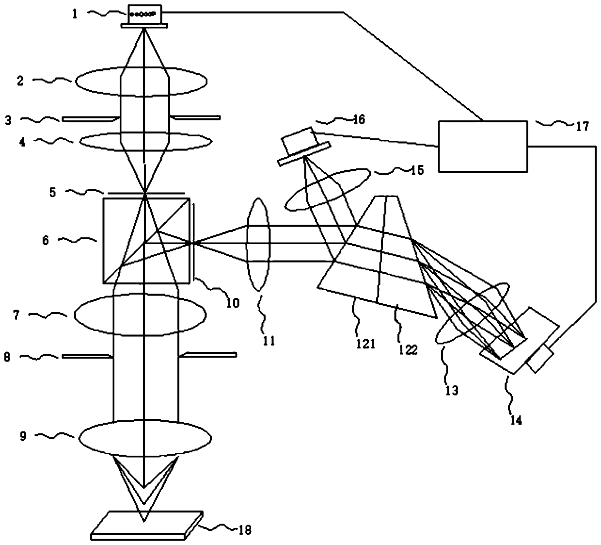
[0037] The dispersive element used in the spectral decoding part of the present invention can be a single dispersive optical element, or a combination of dispersive optical elements. When the dispersive element is a combination of dispersive optical elements, the dispersive element is made of two, three, or multiple optical elements glued together, or the combination of mutually separated optical elements has a dispersion function. Taking the dispersion prism 12 as an example, the dispersion prism 12 may be a single prism or a combination of prisms. It is sufficient that the formed combination has a dispersion function.
[0038] Among them, this embodiment provides a image 3 As an alternative solution shown, the dispersion prism 12 in this embodiment is formed by cementing two prisms (ie, the first cemented dispersion unit 121 and the second cemented dispersion unit 122 ). The structure in which the dispersion prism 12 is composed of three or more prisms glued together will...
Embodiment 3
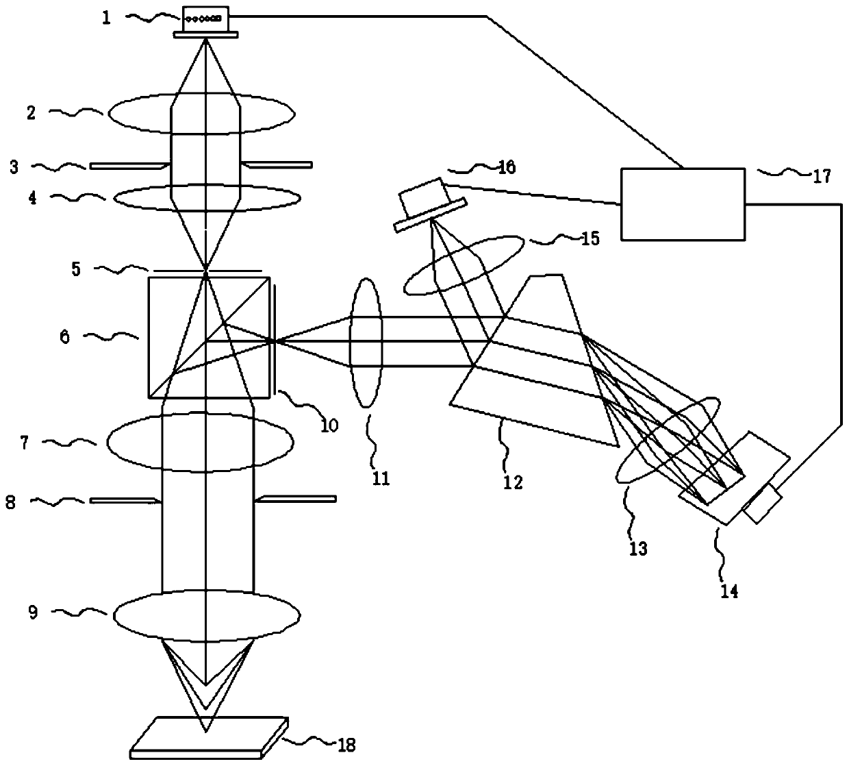
[0041] This embodiment provides a Figure 5 Optical measurement system shown. The composition of this optical measurement system is basically the same as Embodiment 1, the main difference is that the position of the optical prism 6 in the double telecentric objective lens unit is set differently, and the dichroic prism 6 can also be placed in the middle of the first objective lens 7 and the second objective lens 9 Location.
[0042] In this embodiment, the preferred structure of the second optical unit is a bi-telecentric objective lens unit comprising a beam splitter 6 (such as a beam splitter prism), a first objective lens 7 and a second objective lens 9, and the different wavelengths emitted by the second objective lens 9 The beam has axial dispersion in the direction of the optical axis, so that the line lengths corresponding to different heights are the same. The beam splitter 6 is arranged between the first objective lens 7 and the second objective lens 9 , and the bea...
PUM
 Abstract
Description
Claims
Application Information